Part 3: Detailed Working Process of Laser Printing (Step-by-Step Imaging Cycle) |
1. Introduction to the Laser Printing Cycle |
1.1 The laser printing process is a highly coordinated sequence of electrostatic, optical, and thermal operations that convert digital barcode data into a physical printed image. |
1.2 This process is often referred to as the electrophotographic cycle, and it consists of multiple stages that must occur in precise timing and alignment. |
1.3 In barcode label printing, even minor deviations in this cycle can lead to defects such as bar distortion, uneven density, or misalignment, all of which can negatively affect scanning performance. |
1.4 This section provides a detailed, step-by-step analysis of the entire imaging cycle, emphasizing the technical mechanisms involved and their impact on barcode quality. |

|
2. Step 1: Drum Conditioning and Pre-Cleaning |
2.1 Before a new print cycle begins, the photoconductive drum must be prepared to ensure no residual toner or charge remains from previous . |
2.2 A cleaning blade physically scrapes leftover toner from the drum surface, while a discharge lamp or erase LED neutralizes any residual charge. |
2.3 This is critical for barcode printing because any leftover toner can create background noise or unintended marks that interfere with barcode readability. |
2.4 Proper drum conditioning ensures a clean slate for accurate electrostatic image formation. |
3. Step 2: Primary Charging of the Drum |
3.1 Once cleaned, the drum is uniformly charged to a high negative or positive voltage, depending on the printer design. |
3.2 This is typically achieved using a primary charge roller (PCR) or corona wire. |
3.3 The goal is to create a consistent electrostatic field across the entire drum surface. |
3.4 Uniform charging is essential for barcode printing, as variations can lead to inconsistent toner attraction, affecting line thickness and contrast. |
3.5 The voltage level is carefully controlled to balance sensitivity and stability. |

|
4. Step 3: Laser Exposure (Writing the Latent Image) |
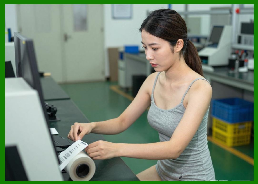
4.1 The laser scanning unit (LSU) emits a finely focused laser beam that is modulated according to the digital barcode data. |
4.2 The laser selectively discharges on the drum surface, reducing the potential in those areas. |
4.3 This creates a latent electrostatic image that represents the barcode pattern, including bars, spaces, and any accompanying text. |
4.4 The precision of laser modulation directly determines the accuracy of barcode elements, including bar width and spacing. |
4.5 High switching of the laser allows for detailed rendering at resolutions such as 600 dpi, 1200 dpi, or higher. |
4.6 Any instability in laser intensity or positioning can result in blurred edges or distorted barcodes. |
|
5. Step 4: Development of the Toner Image |
5.1 The developer unit introduces toner particles to the drum surface. |
5.2 These toner particles are electrically charged and are attracted to the of the drum that were discharged by the laser. |
5.3 The result is a visible toner image that corresponds exactly to the latent electrostatic image. |
5.4 Toner particle size and charge uniformity are critical for achieving sharp barcode edges and consistent density. |
5.5 In barcode printing, uneven toner distribution can lead to such as voids (missing dots) or excessive spreading (dot gain). |

|
6. Step 5: Image Transfer to Label Media |
6.1 The toner image on the drum is transferred to the label material using a transfer roller or corona system. |
6.2 The label is given an opposite electrical charge, which pulls the toner particles from the drum onto the label surface. |
6.3 Precise synchronization between drum rotation and label movement is essential to ensure accurate image placement. |
6.4 In barcode applications, even slight misalignment during transfer can cause skewed or stretched barcodes. |
6.5 The efficiency of toner transfer affects overall print density and completeness of the barcode. |

|
7. Step 6: Separation of Media from the Drum |
7.1 After transfer, the label must be separated cleanly from the drum surface. |
7.2 This is typically achieved using static elimination techniques or mechanical separators. |
7.3 Improper separation can cause toner smearing or distortion of the barcode image. |
7.4 For adhesive label media, this step is particularly critical to prevent sticking or wrapping around the drum. |

|
8. Step 7: Fusing the Toner Image |
8.1 The label passes through the fusing unit, where heat and pressure are applied to permanently bond the toner to the surface. |
8.2 The melts the toner particles, allowing them to flow into the texture of the label material. |
8.3 Pressure ensures even distribution and strong adhesion. |
8.4 In barcode printing, proper fusing is essential for durability and resistance to abrasion. |
8.5 Overheating can cause toner spreading, while insufficient heat can result in weak adhesion and flaking. |

|
9. Step 8: Post-Fusing Cooling and Stabilization |
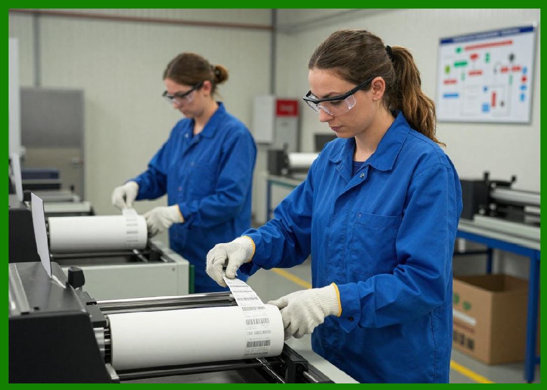
9.1 After fusing, the printed label undergoes a cooling phase to solidify the toner. |
9.2 Cooling stabilizes the image and prevents smudging during handling. |
9.3 Rapid and uniform cooling helps maintain the dimensional accuracy of barcode elements. |
9.4 Thermal expansion and contraction must be carefully managed to avoid distortion. |
|
10. Step 9: Drum Cleaning and Residual Toner Removal |
10.1 After the transfer process, some toner may remain on the drum. |
10.2 The cleaning system removes this residual toner a cleaning blade and collects it in a waste container. |
10.3 Effective cleaning is necessary to prevent ghost images or repeated patterns in subsequent prints. |
10.4 In barcode printing, residual artifacts can interfere with the clarity and contrast of new barcodes. |

|
11. Step 10: Drum Discharge and Reset |
11.1 The drum is exposed to a discharge light source to neutralize any remaining electrical charge. |
11.2 This resets the drum to a neutral state, ready for the next printing cycle. |
11.3 Consistent discharge ensures repeatability and performance across multiple print jobs. |

|
12. Synchronization and Timing Control |
12.1 The entire imaging cycle is controlled by precise timing mechanisms managed by the printer firmware. |
12.2 stage must be synchronized to microsecond-level accuracy to ensure proper alignment of the image. |
12.3 Timing errors can lead to issues such as banding, misregistration, or distorted barcodes. |
12.4 Advanced printers use sensors and feedback systems to monitor and adjust timing dynamically. |

|
13. Impact of the Imaging Cycle on Barcode Quality |
13.1 Each step in the imaging cycle contributes to the final quality of the barcode. |
13.2 Errors in charging, exposure, development, or transfer can lead to defects such as: |
* Uneven bar widths |
* Poor contrast |
* Missing or extra marks |
* Distorted geometry |
13.3 High-quality laser printers are designed to minimize these errors through precise engineering and control systems. |
13.4 consistent imaging cycles are essential for maintaining compliance with barcode quality standards. |

|
Technical Content Summary of Part 3 |
This part provided a comprehensive, step-by-step explanation of the laser printing imaging cycle, also known as the electrophotographic process. The discussion covered all major stages, including drum conditioning, primary charging, laser exposure, toner development, image transfer, media separation, fusing, cooling, and final drum cleaning. |
Each step was analyzed in detail, with a focus on the underlying physical and electrical principles. Special emphasis was placed on how each stage affects barcode quality, including factors such as edge sharpness, contrast, dimensional accuracy, and print consistency. |
The importance of synchronization and timing control was also highlighted, demonstrating how precise coordination between components ensures reliable and repeatable printing performance. |
Overall, this section established a deep understanding of how laser printers convert digital barcode data into high-quality physical labels, laying the foundation for further exploration of optimization techniques and advanced features in subsequent parts. |
 cs@easiersoft.com