Barcode Label Printing: Detailed Explanation of Thermal Transfer Printer Technology |
Part 4 Key Components and Mechanical Structure of Thermal Transfer Printers |
1. Introduction to Printer Mechanical Architecture |
1.1 Importance of Mechanical Design |
1. The mechanical structure of a thermal transfer printer directly determines its reliability, print quality, and operational lifespan. |
2. Even with advanced electronics and materials, poor mechanical design can lead to misalignment, uneven pressure, and print defects. |
3. Industrial-grade printers are engineered to operate continuously under demanding conditions, making mechanical robustness essential. |
1.2 System-Level Perspective |
1. A thermal transfer printer is an integrated electromechanical system. |
2. It combines precision motion control, thermal energy delivery, and material handling. |
3. Each component must operate in tight synchronization to ensure consistent printing. |

|
2. Thermal Printhead Assembly |
2.1 Structural Composition |
1. The printhead consists of a ceramic substrate embedded with resistive heating elements. |
2. These elements are arranged in a linear array across the print width. |
3. Protective coatings shield the heating elements from wear and contamination. |
2.2 Mounting Mechanism |
1. The printhead is mounted on a hinged or spring-loaded bracket. |
2. This allows it to open for ribbon and label loading. |
3. The mechanism ensures consistent pressure when closed. |
2.3 Pressure Adjustment System |
1. Adjustable pressure knobs or screws allow fine-tuning. |
2. Uniform pressure distribution is critical for even printing. |
3. Incorrect pressure leads to uneven print density or premature wear. |

|
3. Platen Roller System |
3.1 Function of the Platen Roller |
1. The platen roller is located directly beneath the printhead. |
2. It supports the label media during printing. |
3. It provides a counterforce for the printhead pressure. |
3.2 Material and Construction |
1. Typically made of rubber or elastomeric materials. |
2. Designed to balance elasticity and durability. |
3. Surface texture affects media grip and print consistency. |
3.3 Wear and Maintenance |
1. Over time, the roller can develop grooves or hard spots. |
2. This leads to inconsistent pressure and print defects. |
3. Regular inspection and replacement are necessary. |

|
4. Ribbon Handling Mechanism |
4.1 Ribbon Supply Spindle |
1. Holds the unused ribbon roll. |
2. Designed for smooth rotation with minimal resistance. |
4.2 Ribbon Take-Up Spindle |
1. Collects the used ribbon after printing. |
2. Maintains proper tension to prevent slack or wrinkles. |
4.3 Ribbon Tension Control |
1. Ensures consistent ribbon movement. |
2. Prevents wrinkles and misalignment. |
3. Achieved through mechanical brakes or electronic control. |

|
5. Media Handling System |
5.1 Media Supply Mechanism |
1. Holds the roll or stack of labels. |
2. Designed for easy loading and alignment. |
5.2 Media Guides |
1. Adjustable guides keep labels aligned during feeding. |
2. Prevent lateral movement that could affect print accuracy. |
5.3 Media Feed Rollers |
1. Drive the label material through the printer. |
2. Must provide consistent traction without damaging the media. |

|
6. Drive System and Motors |
6.1 Types of Motors |
1. Stepper motors are commonly used for precise control. |
2. DC motors may be used in high-speed industrial printers. |
6.2 Motion Control |
1. Motors control the movement of both ribbon and media. |
2. Synchronization is critical to prevent misprints. |
6.3 Gear and Transmission Systems |
1. Transfer motion from motors to rollers and spindles. |
2. Designed to minimize backlash and ensure precision. |

|
7. Sensor Systems |
7.1 Media Sensors |
1. Detect label gaps, black marks, or continuous media. |
2. Ensure correct positioning for each print cycle. |
7.2 Ribbon Sensors |
1. Detect ribbon presence and movement. |
2. Prevent printing without ribbon. |
7.3 Head Open Sensors |
1. Detect whether the printhead is properly closed. |
2. Prevent operation when the printer is not ready. |

|
8. Control Electronics and Circuit Boards |
8.1 Main Control Board |
1. Acts as the central processing unit. |
2. Interprets print commands and controls hardware. |
8.2 Printhead Driver Circuit |
1. Controls the heating elements in the printhead. |
2. Regulates energy delivery for each dot. |
8.3 Power Supply System |
1. Provides stable electrical power. |
2. Must handle high current demands during printing. |

|
9. Structural Frame and Housing |
9.1 Frame Design |
1. Provides structural integrity and stability. |
2. Typically made of metal in industrial printers. |
9.2 Housing Materials |
1. Desktop printers often use plastic enclosures. |
2. Industrial models use metal for durability. |
9.3 Vibration Control |
1. Minimizes mechanical vibrations during operation. |
2. Ensures consistent print quality. |

|
10. Cooling and Thermal Management |
10.1 Heat Generation Sources |
1. Printhead heating elements. |
2. Power electronics. |
10.2 Passive Cooling |
1. Heat dissipation through metal components. |
2. Use of heat sinks. |
10.3 Active Cooling |
1. Fans may be used in high-performance printers. |
2. Prevent overheating during continuous operation. |

|
11. Printhead Lift and Release Mechanism |
11.1 Opening Mechanism |
1. Allows easy access for loading ribbon and labels. |
2. Typically spring-assisted for smooth operation. |
11.2 Locking Mechanism |
1. Ensures the printhead remains securely closed during printing. |
2. Maintains consistent pressure. |

|
12. Ribbon and Media Path Design |
12.1 Path Optimization |
1. Designed to minimize friction and resistance. |
2. Ensures smooth movement of materials. |
12.2 Alignment Considerations |
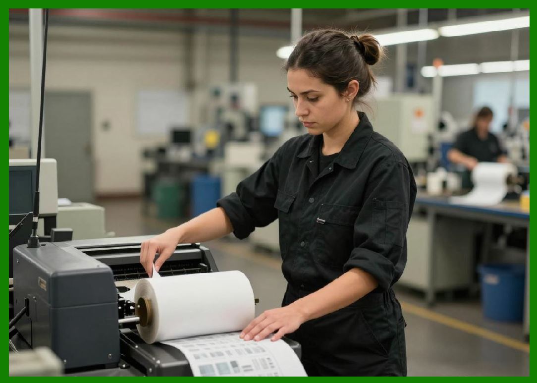
1. Proper alignment prevents wrinkles and skewing. |
|
13. Precision Engineering and Tolerances |
13.1 Mechanical Tolerances |
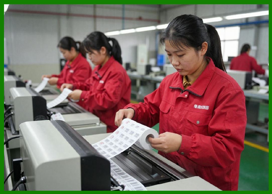
1. Tight tolerances ensure accurate positioning. |
2. Critical for high-resolution printing. |
13.2 Calibration |
1. Printers require calibration for optimal performance. |
2. Includes alignment and pressure adjustments. |
|
14. Durability and Reliability Design |
14.1 Industrial Design Considerations |
1. Built for continuous operation. |
2. to dust, vibration, and temperature variations. |
14.2 Component Lifespan |
1. Printheads have limited life cycles. |
2. Rollers and belts require periodic replacement. |

|
15. Maintenance Accessibility |
15.1 User-Friendly Design |
1. Easy access to key components. |
2. Simplifies cleaning and replacement. |
15.2 Modular Components |
1. Replaceable parts reduce downtime. |

|
16. Integration with External Systems |
16.1 Connectivity Interfaces |
1. USB, Ethernet, Wi-Fi, and Bluetooth. |
2. Enable integration with computers and networks. |
16.2 Expansion Options |
1. Additional modules such as cutters or peelers. |

|
17. Optional Mechanical Features |
17.1 Cutter Mechanism |
1. Automatically cuts labels after printing. |
17.2 Peeler Mechanism |
1. Separates labels from backing for easy application. |
17.3 Rewinder Units |
1. Rewinds printed labels into rolls. |

|
18. Summary of Part 4 |
1. Thermal transfer printers are complex electromechanical systems. |
2. Key components include the printhead, platen roller, ribbon system, and drive mechanisms. |
3. Precision engineering ensures accurate and reliable printing. |
4. Proper design and maintenance are essential for long-term performance. |

|
Next Step |
Part 5 Image Quality, Resolution, and Durability in Thermal Transfer Printing |
The next section will cover: |
* Print resolution (DPI) and its impact |
* Barcode readability and standards |
* Print durability under environmental stress |
* Quality measurement and verification |
 cs@easiersoft.com