Part 11 |
Barcode Encoding Engines and Symbol Generation Systems in Barcode Label Printers Linear Barcode Algorithms, 2D Code Construction, Checksum Computation, Rasterization Pipelines, and Real-Time Image Processing Architectures |
1. Introduction to Barcode Encoding and Symbol Generation |
1.1 |
The barcode encoding engine is the core computational subsystem responsible for transforming human-readable or machine-readable data into precise graphical patterns that can be printed by the thermal printhead. This subsystem sits at the intersection of software algorithms, embedded processing hardware, and real-time raster image generation systems. |
1.2 |
Unlike simple text printing, barcode generation requires strict adherence to mathematical encoding rules defined by international standards. Every barcode symbol must conform to exact spatial, structural, and redundancy constraints to ensure reliable scanning under real-world conditions. |
|
1.3 |
The encoding engine must perform multiple tasks simultaneously, including data validation, encoding transformation, checksum calculation, pattern mapping, scaling, error correction, and raster conversion. These processes must execute in real time to maintain high print throughput. |
1.4 |
Barcode encoding systems directly influence: |
1. Scan reliability |
2. Print resolution independence |
3. Symbol density |
4. Error tolerance |
5. Printer throughput |
6. Memory usage |
7. CPU load |
8. Compatibility with standards |
1.5 |
Modern barcode printers integrate highly optimized encoding libraries, often implemented in firmware, DSP-assisted routines, or hardware acceleration modules within System-on-Chip architectures. |
|
2. Fundamental Structure of Barcode Encoding Systems |
2.1 |
A barcode encoding engine typically operates as a layered processing pipeline. |
2.2 |
The main stages include: |
1. Input data parsing |
2. Symbology selection |
3. Data encoding transformation |
4. Error correction generation |
5. Symbol layout construction |
6. Scaling and dimension adjustment |
7. Raster image conversion |
8. Print buffer integration |
2.3 |
Each stage must operate deterministically to ensure that identical input data always produces identical printed output. |
2.4 |
Encoding pipelines are designed for high efficiency because printers may generate hundreds of labels per minute in industrial environments. |
2.5 |
Memory optimization is critical because large labels containing multiple barcodes, text, and graphics require significant buffering. |
2.6 |
Many modern systems use streaming pipelines to reduce memory overhead. |
2.7 |
The encoding engine is tightly integrated with firmware motion control and printhead timing systems. |
2.8 |
This ensures perfect synchronization between logical symbol generation and physical printing. |

|
3. Linear Barcode Encoding Principles |
3.1 |
Linear barcodes represent data using sequences of parallel bars and spaces of varying widths. |
3.2 |
Each symbology defines a unique encoding structure that maps input data into bar/space patterns. |
3.3 |
Common linear barcode standards include: |
1. Code 39 |
2. Code 128 |
3. EAN-13 |
4. UPC-A |
5. Interleaved 2 of 5 |
6. Codabar |
3.4 |
Each character in a linear barcode is represented by a predefined pattern of narrow and wide elements. |
3.5 |
The encoding process converts characters into binary or multi-width modules. |
3.6 |
For example, Code 39 uses a fixed pattern of nine elements per character, consisting of bars and spaces. |
3.7 |
The total symbol width depends on: |
1. Number of characters |
2. Narrow-to-wide ratio |
3. Quiet zone requirements |
4. Start/stop patterns |
3.8 |
Linear barcode encoding must maintain strict proportional accuracy to ensure scanner interpretability. |

|
4. Code 128 Encoding Engine Architecture |
4.1 |
Code 128 is one of the most widely used high-density linear barcode systems in industrial printing applications. |
4.2 |
It supports full ASCII character encoding and variable-length data compression. |
4.3 |
The encoding process begins with selecting one of three character sets: |
1. Set A (control characters and uppercase) |
2. Set B (full ASCII printable set) |
3. Set C (numeric compression mode) |
4.4 |
Set C is particularly important because it encodes numeric pairs efficiently, reducing symbol length. |
4.5 |
Encoding involves converting input data into weighted symbol values. |
4.6 |
A checksum is computed using modular arithmetic: |
C = (S_0 + \sum_{i=1}^{n} i \cdot S_i) \bmod 103 |
Where: |
* (C) represents checksum value |
* (S_i) represents encoded symbol values |
* (n) represents number of characters |
4.7 |
The checksum ensures detection of misread or corrupted barcode segments. |
4.8 |
The final encoded sequence includes start code, data symbols, checksum, and stop pattern. |
|
5. EAN and UPC Encoding Systems |
5.1 |
EAN and UPC barcodes are widely used in retail and logistics applications. |
5.2 |
These systems encode numeric data with strict formatting rules. |
5.3 |
EAN-13 contains: |
1. Country code |
2. Manufacturer code |
3. Product code |
4. Check digit |
5.4 |
The check digit is calculated using weighted modulo arithmetic: |
C = (10 - ((\sum w_i x_i) \bmod 10)) \bmod 10 |
5.5 |
UPC-A uses a similar structure optimized for North American retail systems. |
5.6 |
Encoding engines must ensure precise digit placement and spacing because retail scanners are highly sensitive to geometric distortion. |
5.7 |
Barcode scaling must preserve proportional relationships between bars and spaces. |
5.8 |
Even minor scaling errors can result in scanning failures at checkout systems. |

|
6. 2D Barcode Encoding Systems |
6.1 |
Two-dimensional barcodes significantly increase data capacity compared with linear barcodes. |
6.2 |
Common 2D symbologies include: |
1. QR Code |
2. Data Matrix |
3. PDF417 |
4. Aztec Code |
6.3 |
2D encoding engines convert input data into matrix-based structures rather than linear sequences. |
6.4 |
These systems divide data into modules arranged in grid patterns. |
6.5 |
QR Code structure includes: |
1. Finder patterns |
2. Alignment patterns |
3. Timing patterns |
4. Data regions |
5. Error correction blocks |
6.6 |
Data Matrix codes use a perimeter 'L-shaped' finder pattern. |
6.7 |
PDF417 uses stacked linear rows forming a large rectangular symbol. |
6.8 |
2D encoding requires significantly more computational processing than linear barcodes. |

|
7. Error Correction and Redundancy Systems |
7.1 |
Error correction is a critical component of modern barcode encoding systems. |
7.2 |
2D barcodes use Reed-Solomon error correction algorithms to recover corrupted data. |
7.3 |
Error correction allows partial damage to labels without losing readability. |
7.4 |
Reed-Solomon encoding operates over finite fields and introduces redundant parity symbols. |
7.5 |
The correction capability depends on redundancy level: |
2t = n - k |
Where: |
* (t) represents correctable symbol errors |
* (n) represents total codewords |
* (k) represents data codewords |
7.6 |
Higher redundancy improves reliability but increases symbol size. |
7.7 |
Encoding engines must balance data capacity with error resilience. |
7.8 |
Industrial environments often require high redundancy levels due to label wear and contamination risks. |
|
8. Rasterization Pipeline Architecture |
8.1 |
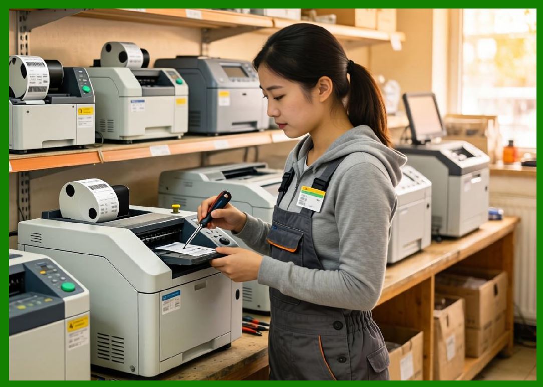
After barcode encoding is complete, the symbol must be converted into a raster bitmap for printhead activation. |
8.2 |
Rasterization transforms vector-based symbol descriptions into pixel-level representations. |
8.3 |
The pipeline includes: |
1. Symbol geometry generation |
2. Scaling and resolution mapping |
3. Pixel grid alignment |
4. Anti-aliasing adjustments |
5. Buffer storage |
8.4 |
Thermal printers operate in a strictly binary pixel domain where each pixel corresponds to a heating element state. |
8.5 |
Raster resolution is typically measured in dots per inch (DPI). |
8.6 |
Higher DPI improves barcode sharpness but increases memory and processing requirements. |
8.7 |
Rasterization must align precisely with printhead timing to avoid spatial distortion. |
8.8 |
Any mismatch between raster generation and motion control results in barcode skew or elongation. |
|
9. Font and Text Rendering Systems |
9.1 |
Barcode labels often include human-readable text alongside machine-readable symbols. |
9.2 |
Text rendering engines convert character codes into bitmap glyphs. |
9.3 |
Common font types include: |
1. Bitmap fonts |
2. Vector fonts |
3. Scalable outline fonts |
9.4 |
Vector fonts provide resolution independence but require raster conversion during printing. |
9.5 |
Font scaling must align with printer DPI to maintain sharp edges. |
9.6 |
Text kerning and spacing algorithms ensure visual readability. |
9.7 |
Embedded printers often store compressed font libraries in flash memory. |
9.8 |
Font rendering is tightly integrated with barcode layout engines. |

|
10. Graphics Compositing and Label Layout Systems |
10.1 |
Modern barcode labels often contain complex layouts including barcodes, text, logos, and graphics. |
10.2 |
Graphics compositing systems combine multiple visual elements into a single print image. |
10.3 |
The layout engine manages: |
1. Object positioning |
2. Layer ordering |
3. Scaling |
4. Rotation |
5. Alignment |
10.4 |
Each element is rendered into a shared raster buffer. |
10.5 |
Alpha blending techniques may be used for grayscale images in advanced printers. |
10.6 |
Memory optimization is essential for large label designs. |
10.7 |
Real-time layout computation must not interfere with print timing. |
10.8 |
Embedded printers often use simplified graphic primitives to reduce processing load. |

|
11. Real-Time Image Processing Constraints |
11.1 |
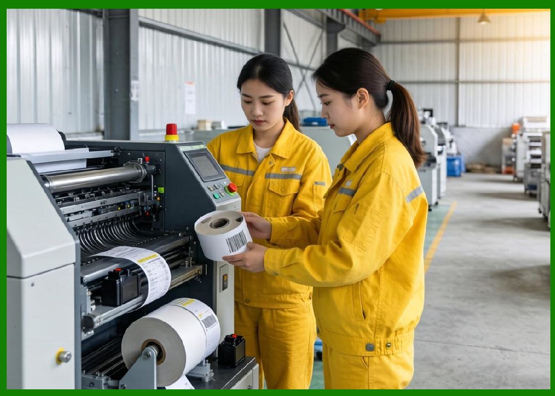
Barcode printers operate under strict real-time constraints because printing cannot be paused without causing label defects. |
11.2 |
Encoding and rasterization must complete before the corresponding print line is required by the printhead driver system. |
11.3 |
Pipeline parallelism is commonly used: |
1. Encoding stage |
2. Rasterization stage |
3. Buffer stage |
4. Print execution stage |
11.4 |
Double buffering allows continuous data flow without interruption. |
11.5 |
Memory bandwidth becomes a critical performance factor. |
11.6 |
Cache optimization improves encoding throughput. |
11.7 |
Interrupt-driven processing coordinates image readiness with motion control timing. |
11.8 |
Timing mismatches can cause partial prints or corrupted symbols. |
|
12. Hardware Acceleration in Encoding Systems |
12.1 |
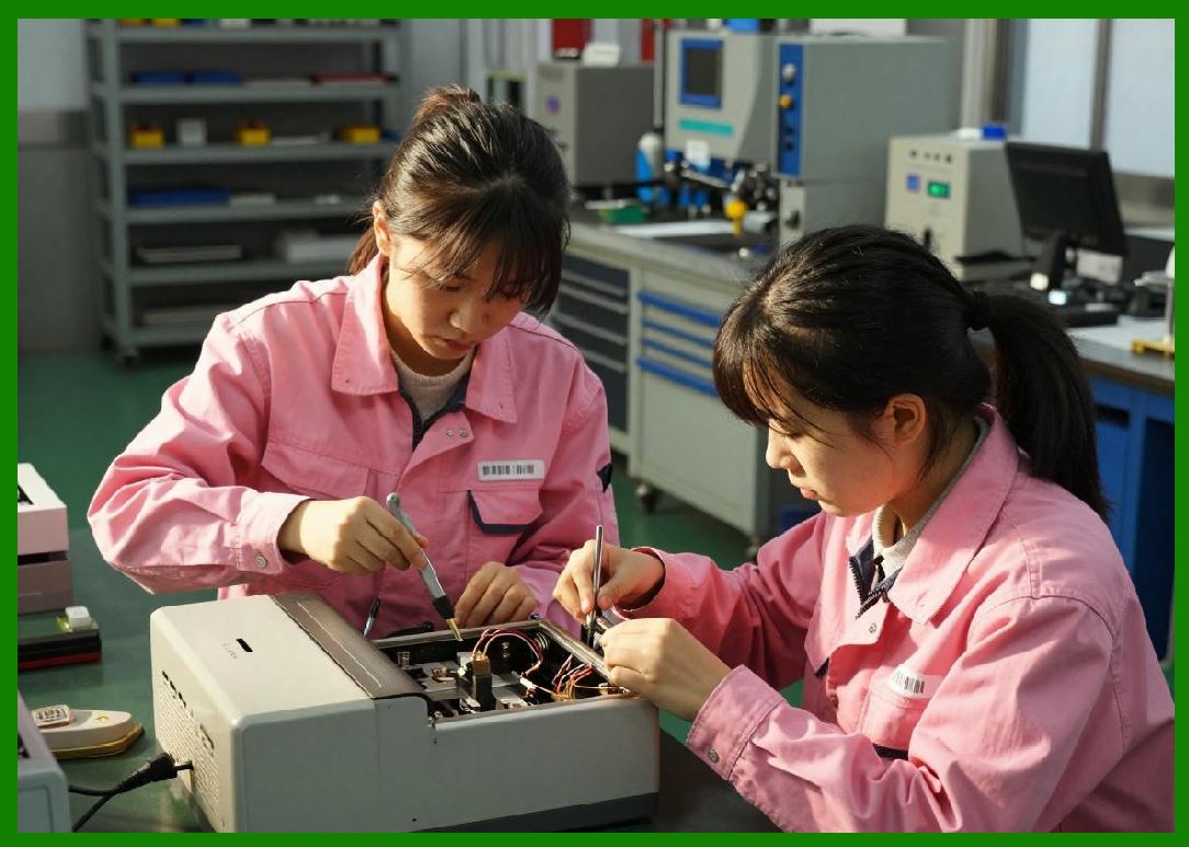
High-performance barcode printers increasingly incorporate hardware acceleration for encoding tasks. |
12.2 |
Acceleration methods include: |
1. DSP processors |
2. FPGA logic |
3. ASIC encoding blocks |
4. SIMD instruction sets |
12.3 |
Hardware acceleration reduces CPU load and improves throughput. |
12.4 |
FPGA-based systems can generate barcode patterns in parallel pipelines. |
12.5 |
ASIC-based encoding engines provide deterministic ultra-low latency performance. |
12.6 |
SIMD instructions accelerate mathematical operations used in checksum and scaling algorithms. |
12.7 |
Hardware acceleration becomes particularly important for high-speed industrial printing lines. |
12.8 |
This enables real-time generation of complex labels without performance bottlenecks. |
|
13. Memory Management in Encoding Engines |
13.1 |
Encoding systems require careful memory management due to large raster buffers. |
13.2 |
Memory allocation strategies include: |
1. Static buffers |
2. Dynamic allocation |
3. Circular buffers |
4. Shared memory pools |
13.3 |
Fragmentation avoidance is critical in embedded systems. |
13.4 |
Cache locality improves processing efficiency during rasterization. |
13.5 |
Compressed intermediate representations reduce memory footprint. |
13.6 |
DMA systems transfer raster data directly to printhead drivers. |
13.7 |
Efficient memory usage directly affects maximum print speed capability. |
13.8 |
Embedded systems must balance memory constraints with label complexity requirements. |

|
14. Error Detection in Encoding Pipelines |
14.1 |
Encoding systems include internal validation mechanisms to ensure symbol correctness. |
14.2 |
Error detection methods include: |
1. Checksum verification |
2. Format validation |
3. Data range checking |
4. Symbol structure validation |
14.3 |
Invalid encoding inputs are rejected before printing begins. |
14.4 |
Firmware may generate error reports for host systems. |
14.5 |
Redundant encoding verification improves industrial reliability. |
14.6 |
Self-test routines validate encoding engine integrity during startup. |
14.7 |
Continuous validation prevents propagation of corrupted print jobs. |
14.8 |
This is essential for mission-critical applications such as healthcare and logistics tracking. |

|
15. Future Trends in Barcode Encoding Systems |
15.1 |
Barcode encoding systems will continue evolving toward greater automation, intelligence, and integration with digital ecosystems. |
15.2 |
AI-assisted encoding may optimize symbol placement, density, and readability based on environmental conditions. |
15.3 |
Dynamic adaptive encoding could adjust barcode structure in real time based on printer performance and media type. |
15.4 |
Cloud-based encoding services may generate optimized print instructions remotely. |
15.5 |
Quantum-resistant cryptographic encoding may appear in secure labeling applications. |
15.6 |
Hybrid human-machine-readable systems may integrate multiple identification technologies into unified label formats. |
15.7 |
Despite these advancements, the core objective remains unchanged: converting structured data into highly reliable, machine-readable printed symbols with absolute geometric precision. |

|
Technical Content Summary |
This part explored the detailed engineering principles of barcode encoding engines and symbol generation systems inside barcode label printers. The discussion examined linear barcode encoding methods, Code 128 structure, EAN/UPC computation, 2D barcode construction, error correction algorithms, rasterization pipelines, font rendering systems, and graphics compositing architectures. |
The article described how encoding systems transform structured digital data into precise printable patterns while maintaining strict compliance with international barcode standards. It also analyzed checksum mathematics, Reed-Solomon error correction, memory management strategies, and hardware acceleration techniques used in modern embedded printing systems. |
Additionally, this section explained how real-time image processing pipelines ensure synchronization between encoding, rasterization, and printhead activation in high-speed industrial barcode printers. |
The next part will focus on thermal print quality control systems inside barcode label printers, including dot energy calibration, thermal compensation curves, media-dependent adjustment models, print density regulation, and closed-loop feedback optimization systems. |
 cs@easiersoft.com