Part 20 |
Sensor Systems and Feedback Control in Barcode Label Printers Optical Detection, Encoder Feedback Loops, Calibration Systems, Closed-Loop Correction, and Real-Time Adaptive Alignment |
1. Introduction to Sensor and Feedback Systems |
1.1 |
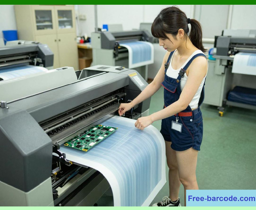
Sensor systems and feedback control mechanisms are essential components in barcode label printers because they provide real-time awareness of mechanical position, media movement, print alignment, and system health. Without sensors, a printer would operate in an open-loop mode, relying purely on assumptions rather than physical reality. |
1.2 |
Barcode printing requires extremely high positional accuracy, often within fractions of a millimeter. This level of precision cannot be achieved through open-loop control alone, especially under varying mechanical loads, media types, and environmental conditions. |
|
1.3 |
Sensor feedback systems continuously correct deviations between expected and actual system behavior, ensuring stable alignment between: |
1. Printhead activation timing |
2. Media position |
3. Label boundaries |
4. RFID tag location |
5. Encoder-based motion tracking |
1.4 |
These systems directly affect: |
* Barcode scan reliability |
* Print registration accuracy |
* Label alignment consistency |
* Throughput stability |
* Mechanical wear compensation |
* System fault detection |
* Adaptive calibration performance |
* Industrial automation integration |
1.5 |
Modern printers rely heavily on closed-loop control systems combining optical, mechanical, and electronic sensors. |
|
2. Fundamental Principles of Feedback Control |
2.1 |
Feedback control systems operate by continuously measuring actual system output and comparing it with a desired reference value. |
2.2 |
The basic control relationship can be expressed as: |
e(t) = r(t) - y(t) |
Where: |
* (e(t)) represents error signal |
* (r(t)) represents reference (desired position or timing) |
* (y(t)) represents measured output |
2.3 |
The system adjusts its behavior based on this error signal to minimize deviation. |
2.4 |
In barcode printers, feedback loops operate continuously during printing to maintain alignment. |
|
2.5 |
Small deviations are corrected in real time to prevent cumulative errors. |
2.6 |
Feedback control improves robustness against mechanical wear and environmental variation. |
2.7 |
Multiple feedback loops operate simultaneously across different subsystems. |
2.8 |
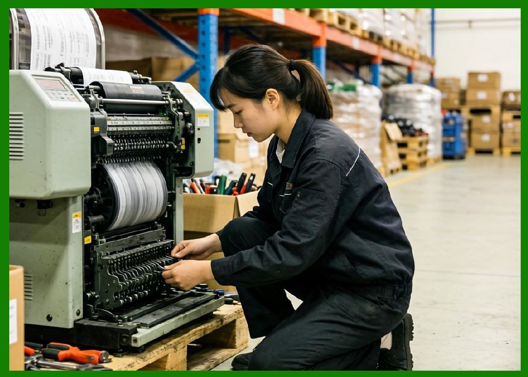
Closed-loop control is fundamental for industrial-grade precision printing. |
|
3. Optical Sensor Systems in Media Detection |
3.1 |
Optical sensors are widely used in barcode printers to detect media position, label gaps, and registration marks. |
3.2 |
These sensors typically operate using light emission and reflection or transmission measurement principles. |
3.3 |
Common optical sensor types include: |
1. Gap sensors |
2. Black mark sensors |
3. Reflective sensors |
4. Transmission sensors |
3.4 |
Gap sensors detect differences between label material and backing liner. |
3.5 |
Black mark sensors detect printed reference marks on media surfaces. |
3.6 |
Reflective sensors measure light reflected from the media surface. |
3.7 |
Transmission sensors detect light passing through translucent media gaps. |
3.8 |
Accurate optical sensing is essential for label alignment and print start positioning. |

|
4. Encoder-Based Motion Feedback Systems |
4.1 |
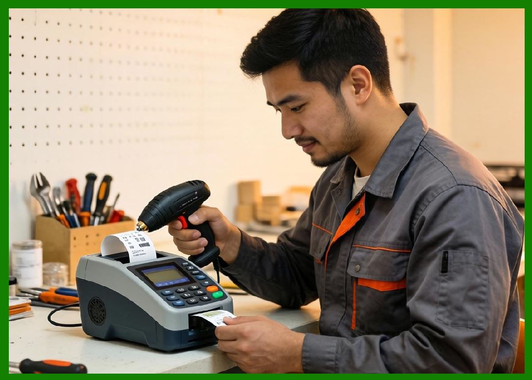
Encoders are critical components in barcode printer motion systems, providing precise measurement of roller or motor movement. |
4.2 |
Encoders convert mechanical motion into electrical pulse signals. |
4.3 |
There are two primary encoder types: |
1. Incremental encoders |
2. Absolute encoders |
4.4 |
Incremental encoders measure relative movement using pulse counts. |
4.5 |
Absolute encoders provide exact positional data at all times. |
4.6 |
Encoder resolution determines motion precision and feed accuracy. |
4.7 |
The relationship between encoder pulses and displacement can be expressed as: |
d = N \cdot p |
Where: |
* (d) represents displacement |
* (N) represents pulse count |
* (p) represents distance per pulse |
4.8 |
Encoders form the backbone of closed-loop motion control systems. |
|
5. Closed-Loop Media Position Control |
5.1 |
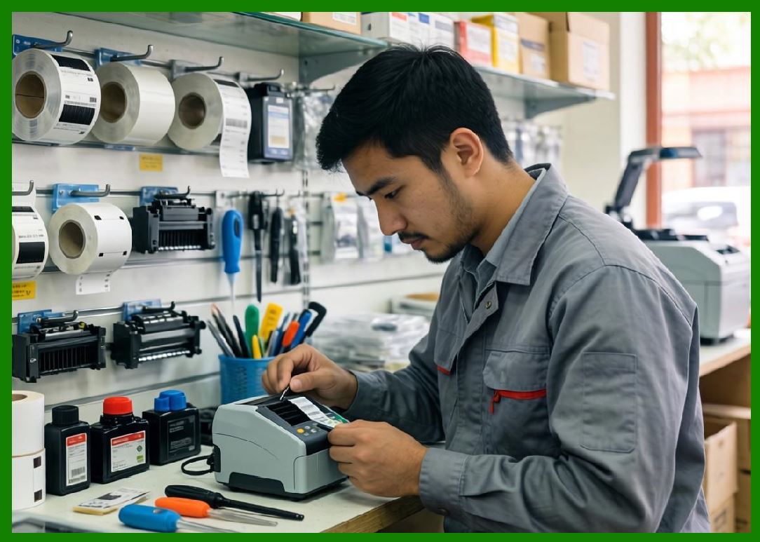
Closed-loop control ensures that media movement matches intended displacement precisely. |
5.2 |
The system continuously compares encoder feedback with target movement values. |
5.3 |
If deviation occurs, corrective adjustments are applied immediately. |
5.4 |
Closed-loop control improves accuracy under varying loads and friction conditions. |
5.5 |
It also compensates for mechanical wear and environmental changes. |
5.6 |
Feedback-based correction prevents cumulative feed errors. |
5.7 |
High-end systems maintain sub-millimeter positioning accuracy. |
5.8 |
Closed-loop media control is essential for high-speed printing stability. |
|
6. Print Registration and Alignment Correction Systems |
6.1 |
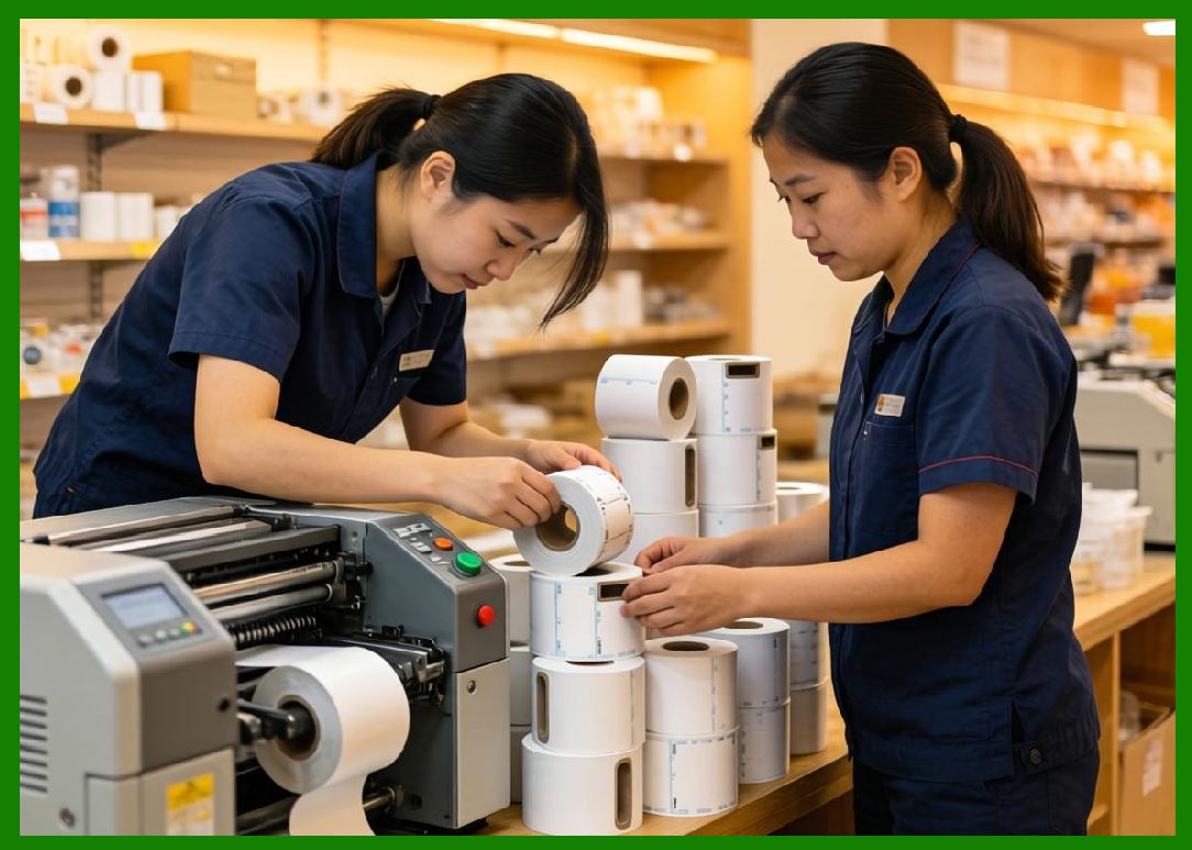
Print registration ensures that printed content aligns precisely with label boundaries. |
6.2 |
Misalignment can result in: |
1. Cropped barcodes |
2. Off-center printing |
3. Partial label printing |
4. Scan failure |
6.3 |
Registration systems use sensor data to detect label boundaries in real time. |
6.4 |
Firmware adjusts print start timing based on detected position. |
6.5 |
Micro-adjustments are applied dynamically during operation. |
6.6 |
Alignment correction compensates for mechanical drift. |
6.7 |
Registration accuracy improves consistency across large print batches. |
6.8 |
Proper alignment is critical for barcode readability standards. |
|
7. Real-Time Calibration Systems |
7.1 |
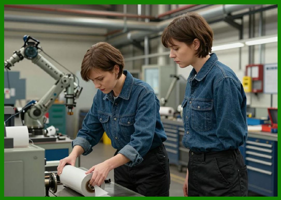
Calibration systems ensure that sensor and motion subsystems maintain accuracy over time. |
7.2 |
Calibration procedures include: |
1. Media feed calibration |
2. Sensor threshold calibration |
3. Printhead alignment calibration |
4. Encoder offset correction |
7.3 |
Calibration may occur automatically during startup or periodically during operation. |
7.4 |
Environmental factors such as temperature and humidity can affect calibration stability. |
7.5 |
Adaptive calibration systems continuously refine system parameters. |
7.6 |
Calibration data is stored in non-volatile memory for persistence. |
7.7 |
Accurate calibration reduces cumulative error drift. |
7.8 |
Calibration is essential for long-term industrial reliability. |
|
8. Multi-Sensor Fusion Systems |
8.1 |
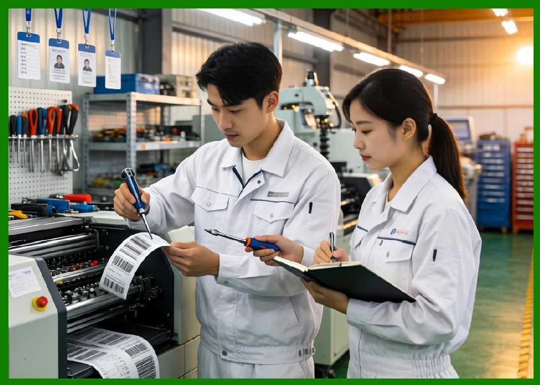
Advanced printers often combine multiple sensor inputs to improve accuracy and reliability. |
8.2 |
Sensor fusion integrates data from: |
1. Optical sensors |
2. Encoders |
3. Thermal feedback systems |
4. RFID position detection |
8.3 |
Combining multiple data sources reduces uncertainty. |
8.4 |
Sensor fusion algorithms filter noise and improve stability. |
8.5 |
Weighted averaging may be used to combine redundant signals. |
8.6 |
Conflict resolution logic handles inconsistent sensor readings. |
8.7 |
Fusion systems improve robustness in complex environments. |
8.8 |
This approach enhances overall system intelligence. |
|
9. Error Detection and Drift Compensation |
9.1 |
Over time, mechanical systems exhibit drift due to wear and environmental changes. |
9.2 |
Drift may affect: |
1. Feed accuracy |
2. Sensor alignment |
3. Printhead positioning |
4. Encoder calibration |
9.3 |
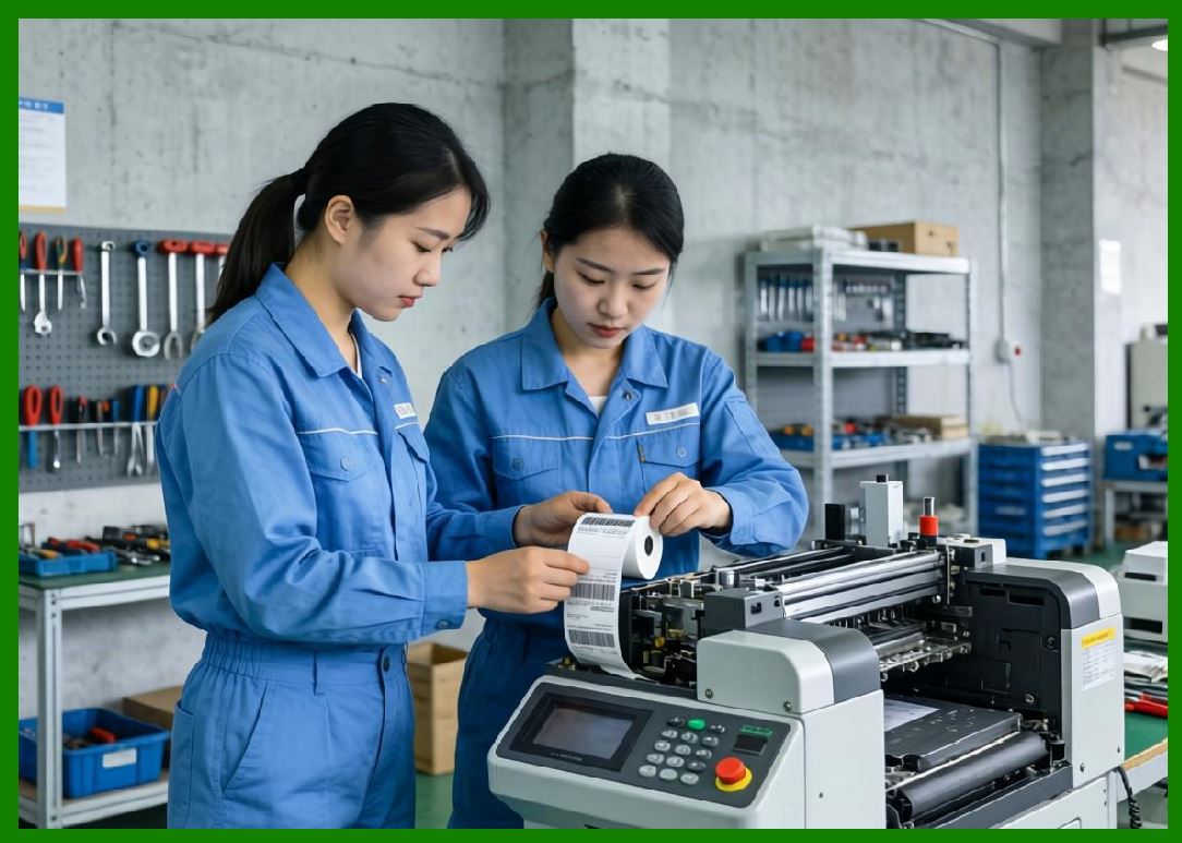
Feedback systems detect drift by comparing expected vs actual behavior. |
9.4 |
Compensation mechanisms adjust system parameters dynamically. |
9.5 |
Long-term drift correction ensures stable output quality. |
9.6 |
Predictive models help anticipate future deviations. |
9.7 |
Firmware continuously updates correction coefficients. |
9.8 |
Drift compensation is essential for sustained industrial accuracy. |
|
10. Dynamic Alignment Correction During Printing |
10.1 |
Some advanced systems perform alignment correction during active printing. |
10.2 |
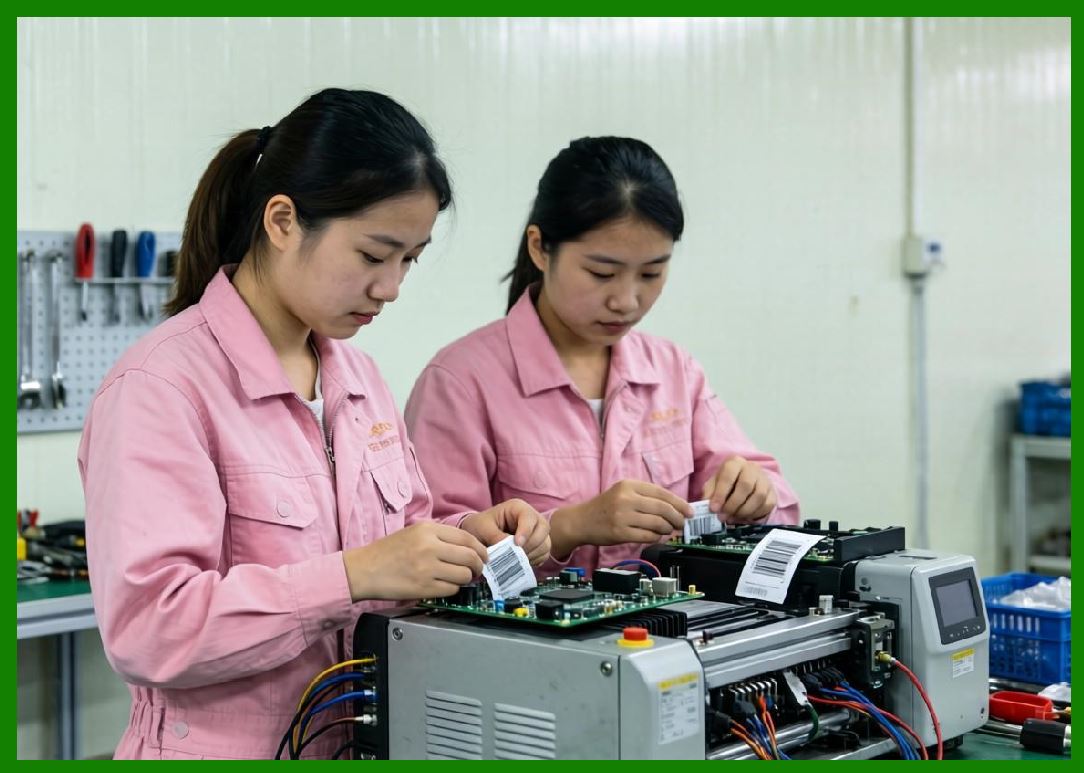
This involves micro-adjustments in real time based on sensor feedback. |
10.3 |
Corrections may affect: |
1. Print timing |
2. Media feed speed |
3. Dot activation alignment |
10.4 |
These adjustments occur at millisecond or microsecond scale. |
10.5 |
Real-time correction prevents visible artifacts in output. |
10.6 |
Dynamic systems improve resilience under variable conditions. |
10.7 |
Correction algorithms must avoid introducing oscillations. |
10.8 |
Stability is maintained through controlled feedback damping. |
|
11. Noise Filtering and Signal Stabilization |
11.1 |
Sensor signals often contain electrical or mechanical noise. |
11.2 |
Noise sources include: |
1. Motor vibration |
2. Electrical switching |
3. Ambient light interference |
4. RF emissions |
11.3 |
Filtering techniques include: |
* Low-pass filters |
* Digital smoothing algorithms |
* Signal averaging |
* Threshold hysteresis |
11.4 |
Noise reduction improves measurement accuracy. |
11.5 |
Improper filtering can introduce latency in feedback loops. |
11.6 |
Balanced filtering is essential for real-time control. |
11.7 |
Signal stability directly affects print quality. |
11.8 |
Robust filtering enhances system reliability. |

|
12. Sensor Failure Detection and Redundancy |
12.1 |
Sensor systems must detect their own failure conditions to avoid incorrect control decisions. |
12.2 |
Failure types include: |
1. Signal loss |
2. Drift beyond tolerance |
3. Electrical short or open circuit |
4. Calibration mismatch |
12.3 |
Redundant sensors may be used for cross-validation. |
12.4 |
Disagreement between sensors triggers fault conditions. |
12.5 |
Firmware isolates faulty components to maintain operation. |
12.6 |
Fail-safe modes reduce system functionality rather than risk incorrect output. |
12.7 |
Redundancy improves industrial reliability. |
12.8 |
Sensor diagnostics are critical for system safety. |

|
13. Adaptive Feedback Control Algorithms |
13.1 |
Adaptive control systems adjust parameters dynamically based on operating conditions. |
13.2 |
These systems modify: |
1. Feed rates |
2. Print timing |
3. Sensor thresholds |
4. Motor acceleration profiles |
13.3 |
Adaptive algorithms respond to changes in: |
* Media type |
* Temperature |
* Wear conditions |
* Load variation |
13.4 |
Machine learning techniques may be used in advanced systems. |
13.5 |
Adaptive control improves long-term consistency. |
13.6 |
System behavior becomes more stable over time. |
13.7 |
Real-time adaptation reduces need for manual calibration. |
13.8 |
This is a key trend in modern printer intelligence. |

|
14. Integration of Feedback Systems with Firmware |
14.1 |
Feedback systems are tightly integrated into firmware architecture. |
14.2 |
Sensor data is processed in real time by RTOS tasks and interrupt handlers. |
14.3 |
Control loops operate at high frequency to ensure rapid response. |
14.4 |
Firmware maintains synchronization between multiple feedback domains. |
14.5 |
Data from sensors influences motion, printing, and RFID subsystems. |
14.6 |
Integration ensures system-wide coherence. |
14.7 |
Efficient firmware design is essential for real-time feedback control. |
14.8 |
This integration defines overall system precision. |

|
15. Future Trends in Sensor and Feedback Systems |
15.1 |
Future barcode printers will use increasingly intelligent and autonomous feedback systems. |
15.2 |
Emerging developments include: |
* AI-based predictive correction |
* Self-calibrating sensor networks |
* Multi-dimensional sensor fusion |
* Real-time digital twin modeling |
15.3 |
Advanced systems may simulate printer behavior digitally before execution. |
15.4 |
Ultra-precise optical and motion sensors will further reduce error margins. |
15.5 |
Edge intelligence will enable autonomous adjustment without external input. |
15.6 |
Fully self-correcting printers may eliminate manual calibration entirely. |
15.7 |
Despite technological advancement, the core principle remains unchanged: continuous real-time correction of physical behavior based on sensor feedback to ensure deterministic, high-precision barcode output. |

|
Technical Content Summary |
This part explored the detailed engineering principles of sensor systems and feedback control in barcode label printers. The discussion covered optical sensing, encoder feedback, closed-loop control theory, registration alignment systems, real-time calibration, multi-sensor fusion, drift compensation, dynamic correction, noise filtering, redundancy, and adaptive control algorithms. |
The article explained how modern printers rely on tightly integrated feedback loops to maintain precise synchronization between mechanical motion, thermal activation, and media positioning. It also analyzed how real-time correction systems ensure consistent barcode quality under variable industrial conditions. |
Additionally, this section described how sensor-driven control architectures form the foundation of accuracy, reliability, and adaptability in advanced barcode printing systems. |
The next part will focus on thermal dynamics and heat management in printhead systems, including heat diffusion modeling, thermal response curves, energy dissipation strategies, and material science aspects of thermal printing elements. |
 cs@easiersoft.com