Part 3 |
Direct Thermal Barcode Printers Thermal Physics, Semiconductor Printheads, and Electronic Control Circuit Design |
1. Introduction to Direct Thermal Barcode Printing |
1.1 |
Direct thermal printing represented one of the most important technological breakthroughs in the history of barcode label printers. Unlike impact printers that relied on mechanical force and ink ribbons, direct thermal printers generated images by selectively heating chemically treated thermal paper. This eliminated many moving parts, reduced mechanical wear, lowered acoustic noise, and significantly improved barcode sharpness and reliability. |
1.2 |
The development of direct thermal printing fundamentally transformed industrial barcode systems. Warehouses, shipping companies, hospitals, retail stores, laboratories, and transportation industries rapidly adopted thermal barcode printers because they provided higher resolution, faster printing speed, and lower maintenance requirements compared with impact-based technologies. |

|
1.3 |
The invention of thermal barcode printers was closely connected to advances in semiconductor materials, ceramic substrate manufacturing, resistive thin-film deposition, and embedded microcontroller systems. Direct thermal printing required extremely precise electronic control because image quality depended on accurately managing microscopic heating events occurring within milliseconds. |
1.4 |
Early thermal barcode printers were initially limited by thermal paper durability, printhead lifespan, and power consumption. However, continuous improvements in thermal chemistry, printhead manufacturing, and energy management circuits gradually overcame these limitations. |
1.5 |
Modern direct thermal barcode printers still operate according to the same fundamental principles established during the early development period. Although contemporary systems are vastly more advanced, the underlying interaction between electrical energy, thermal transfer, and chemically reactive media remains essentially unchanged. |

|
2. Fundamental Principle of Direct Thermal Printing |
2.1 |
Direct thermal printing operates by applying heat directly to specially coated thermal paper. The paper contains heat-sensitive chemical compounds that undergo a color-forming reaction when exposed to localized heating. |
2.2 |
The printer contains a thermal printhead consisting of a linear array of microscopic resistive heating elements. Each element acts as an individually addressable pixel generator. |
2.3 |
When electrical current flows through a heating resistor, electrical energy converts into heat according to Joule Law: |
P = I^2R |
Where: |
* (P) represents thermal power |
* (I) represents electrical current |
* (R) represents resistance |

|
2.4 |
This heat transfers into the thermal paper coating, causing a localized chemical reaction that darkens the paper surface. By selectively energizing different heating elements while moving the paper beneath the printhead, the printer forms barcode patterns and text images. |
2.5 |
The duration of heating pulses strongly influences image darkness. Short pulses produce lighter marks, while longer pulses generate darker images. Therefore, pulse-width timing became one of the most important aspects of thermal printer circuit design. |
2.6 |
Since barcode readability depends heavily on edge sharpness and contrast ratio, engineers had to carefully optimize heating energy, print speed, thermal conductivity, and media characteristics. |
2.7 |
The simplicity of direct thermal printing provided major reliability advantages because no ink ribbon, impact hammer, or toner transfer mechanism was required. |

|
3. Structure of the Thermal Printhead |
3.1 |
The thermal printhead became the central component of direct thermal barcode printers. Its design required advanced semiconductor manufacturing techniques combined with precision ceramic engineering. |
3.2 |
A thermal printhead typically consists of: |
1. Ceramic substrate |
2. Thin-film resistive heating elements |
3. Conductive traces |
4. Driver integrated circuits |
5. Protective overcoat layer |
6. Heat sink structure |
7. Flexible electrical connector |

|
3.3 |
The ceramic substrate provides both electrical insulation and thermal stability. Aluminum oxide ceramic became widely used because it offers excellent heat resistance, dimensional stability, and electrical insulation properties. |
3.4 |
Microscopic resistive elements are deposited onto the substrate using thin-film semiconductor fabrication methods similar to integrated circuit manufacturing processes. |
3.5 |
Each resistor functions as an individual heating pixel. The density of these pixels determines print resolution. Common early resolutions included: |
1. 203 dpi (dots per inch) |
2. 300 dpi |
3. 406 dpi |
3.6 |
Higher print resolution allowed narrower barcode elements and improved scanner reliability, especially for high-density symbologies. |
3.7 |
The printhead assembly also included integrated driver electronics mounted close to the heating elements to minimize signal propagation delays and electrical noise. |

|
4. Thin-Film Resistor Technology |
4.1 |
The heating elements inside thermal printheads are specialized thin-film resistors engineered for rapid thermal response and long operational life. |
4.2 |
These resistors are typically formed using materials such as tantalum nitride, ruthenium oxide, or other carefully controlled resistive compounds deposited onto ceramic substrates. |
4.3 |
The resistance value of each element must remain highly consistent across the printhead array. Variations in resistance produce uneven heating, leading to inconsistent barcode darkness and poor edge quality. |

|
4.4 |
The heat generated by a resistor follows: |
Q = I^2Rt |
Where: |
* (Q) represents heat energy |
* (I) represents current |
* (R) represents resistance |
* (t) represents pulse duration |
4.5 |
Because thermal response times occur within microseconds or milliseconds, printhead driver circuits require extremely fast switching performance. |
4.6 |
The resistor geometry also affects thermal efficiency. Engineers optimized resistor width, thickness, and length to balance heating speed, durability, and power consumption. |
4.7 |
Protective overcoat layers shielded the resistors from mechanical abrasion caused by continuous contact with moving label media. |

|
5. Thermal Paper Chemistry |
5.1 |
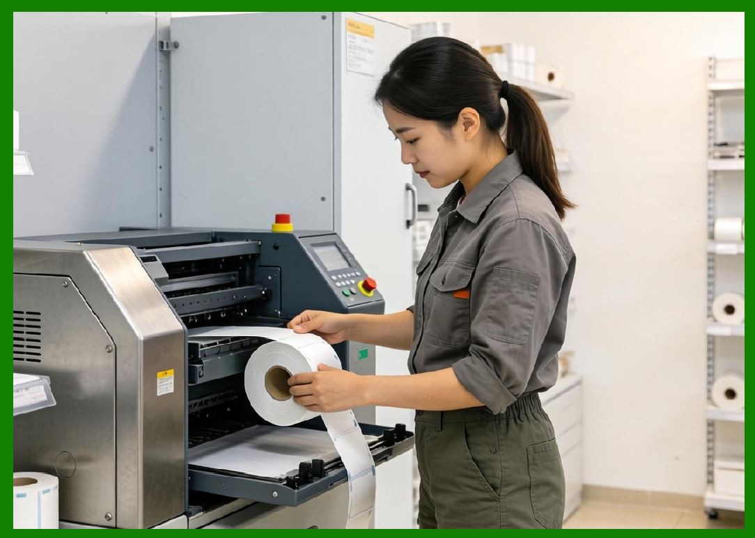
Direct thermal printing depends heavily on the chemical structure of thermal paper. The paper contains multiple specialized coating layers engineered to react predictably under controlled heating conditions. |
5.2 |
A typical thermal paper structure includes: |
1. Base paper layer |
2. Primer coating |
3. Heat-sensitive reactive layer |
4. Protective top coating |
5.3 |
The heat-sensitive layer contains several important chemical components: |
1. Colorless dye molecules (leuco dyes) |
2. Color developers |
3. Sensitizers |
4. Stabilizers |
5.4 |
When heated, the sensitizer melts and allows the dye and developer to chemically react, producing a dark visible image. |
5.5 |
The reaction temperature must remain carefully controlled. If heating is insufficient, the image becomes faint. If excessive heating occurs, bar edges spread and barcode readability decreases. |
5.6 |
Environmental conditions strongly affect thermal paper behavior. High humidity, ultraviolet exposure, chemical contamination, and elevated temperatures can degrade printed images over time. |
5.7 |
Engineers therefore developed adaptive energy control algorithms that compensated for environmental variations and paper manufacturing tolerances. |
|
6. Thermal Energy Control Circuits |
6.1 |
One of the most critical engineering challenges in direct thermal barcode printers involved precisely controlling thermal energy delivered to each print pixel. |
6.2 |
Excessive heating caused: |
1. Blurred barcode edges |
2. Paper scorching |
3. Excessive power consumption |
4. Reduced printhead lifespan |
6.3 |
Insufficient heating caused: |
1. Poor contrast |
2. Scanner read failures |
3. Incomplete barcode formation |
4. Weak image durability |
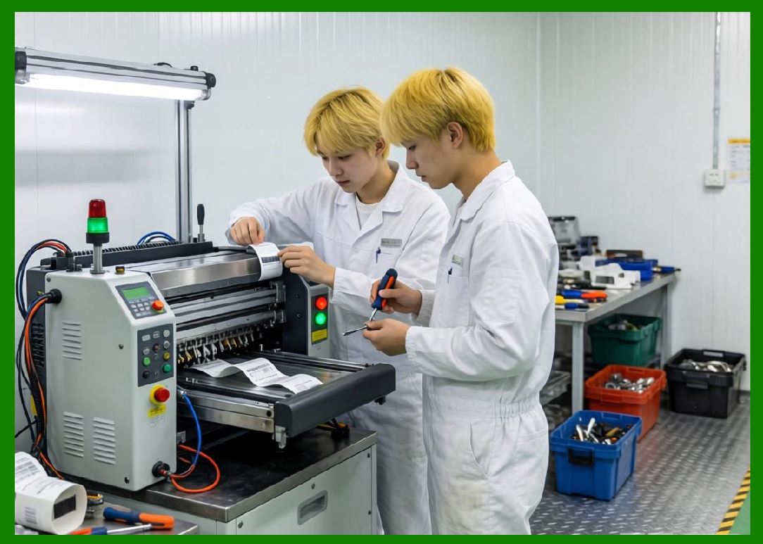
6.4 |
To achieve optimal results, printer electronics controlled three primary variables: |
1. Heating current |
2. Pulse duration |
3. Pulse timing sequence |
|
6.5 |
Pulse-width modulation (PWM) became widely used for thermal energy regulation. The printhead driver rapidly switched power on and off, controlling effective heating energy through duty cycle adjustment. |
6.6 |
The average power delivered during PWM operation follows: |
P_{avg} = D \times P_{max} |
Where: |
* (P_{avg}) represents average power |
* (D) represents duty cycle |
* (P_{max}) represents maximum instantaneous power |
6.7 |
Dynamic energy adjustment algorithms compensated for varying print density. Large solid black regions required different energy management compared with isolated barcode lines. |
6.8 |
Advanced systems also monitored printhead temperature in real time and automatically reduced energy levels during overheating conditions. |
7. Printhead Driver Integrated Circuits |
7.1 |
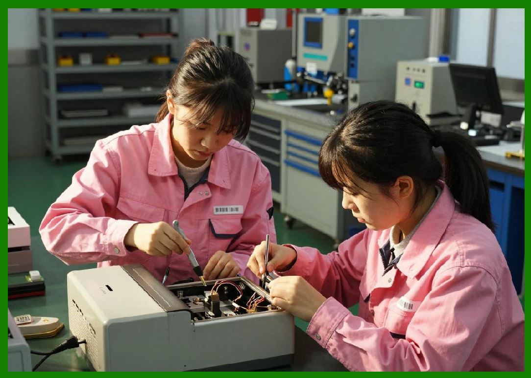
Thermal printheads contain hundreds or thousands of heating elements, each requiring individual electrical control. Direct processor control of every resistor would be impractical, so specialized driver integrated circuits were developed. |
7.2 |
These driver ICs functioned as high-speed switching arrays capable of delivering large current pulses to selected heating elements. |
7.3 |
The driver architecture typically included: |
1. Shift registers |
2. Latch circuits |
3. Output transistors |
4. Current control circuitry |
5. Thermal protection systems |
7.4 |
Image data was serially shifted into internal registers and then latched simultaneously to activate selected heating elements. |
7.5 |
This serial loading architecture minimized interconnect complexity between the processor and printhead assembly. |
7.6 |
Output driver stages often used DMOS transistor technology because it provided low conduction losses and fast switching performance. |
7.7 |
Thermal shutdown circuits protected the printhead from catastrophic overheating by disabling outputs when temperature thresholds were exceeded. |
7.8 |
As print resolution increased, driver IC integration became increasingly sophisticated to handle higher channel densities and faster data transfer rates. |
|
8. Data Buffering and Raster Image Generation |
8.1 |
Thermal barcode printers operate using raster image generation methods. Each horizontal print line is represented as a bitmap containing binary pixel data. |
8.2 |
The printer processor converts barcode information into rasterized image lines stored temporarily in memory buffers. |
8.3 |
Each pixel corresponds to a single heating element position within the printhead array. A binary value determines whether that pixel receives heating energy. |
8.4 |
Memory buffering became extremely important because printing operations required continuous high-speed data delivery to the printhead. |
8.5 |
Early thermal printers often used static RAM chips for line buffering. Limited memory capacity restricted maximum label complexity and graphics support. |
8.6 |
DMA (Direct Memory Access) systems later improved throughput by transferring image data directly between memory and printhead drivers without excessive CPU involvement. |
8.7 |
Sophisticated rasterization algorithms also compensated for thermal spreading effects that could distort barcode dimensions. |

|
9. Media Motion Control Systems |
9.1 |
Accurate barcode generation required precise synchronization between printhead operation and media movement. |
9.2 |
Thermal printers typically used stepper motors to advance label stock beneath the printhead in carefully controlled increments. |
9.3 |
Each motor step corresponded to a specific vertical movement distance, allowing highly repeatable print positioning. |
9.4 |
The print resolution in the feed direction depended directly on motor step accuracy and platen roller diameter precision. |
9.5 |
Stepper motor driver circuits sequentially energized motor windings according to digitally generated timing patterns. |
9.6 |
Microstepping techniques gradually emerged to reduce vibration and improve motion smoothness. These systems used analog current control to produce intermediate rotational positions. |
9.7 |
Media transport systems also included pressure rollers ensuring consistent contact between paper and printhead surfaces. |
9.8 |
Encoder feedback systems monitored actual movement and detected slippage or jam conditions. |
|
10. Thermal Management in Direct Thermal Printers |
10.1 |
Thermal management became one of the most critical aspects of direct thermal printer engineering. Excessive heat accumulation degraded print quality and shortened component lifespan. |
10.2 |
Heat originated from multiple sources: |
1. Printhead resistors |
2. Driver transistors |
3. Power supplies |
4. Motor systems |
10.3 |
The printhead itself experienced repeated rapid heating cycles capable of generating significant thermal stress. |
10.4 |
Engineers introduced aluminum heat sinks and thermally conductive mounting structures to dissipate excess energy. |
10.5 |
Temperature sensors embedded within the printhead monitored operating conditions continuously. |
10.6 |
Firmware algorithms dynamically adjusted print speed and heating energy according to measured temperature. |
10.7 |
Thermal equalization techniques distributed heating activity across the printhead to reduce localized hot spots. |
10.8 |
Cooling airflow design also became increasingly important in high-speed industrial printers. |

|
11. Power Supply Challenges in Thermal Printers |
11.1 |
Thermal barcode printers imposed demanding requirements on power supply systems because printhead elements consumed substantial instantaneous current. |
11.2 |
Large numbers of heating resistors could activate simultaneously during dense barcode or graphics printing operations. |
11.3 |
Power supply circuits therefore required: |
1. High current capability |
2. Fast transient response |
3. Low voltage ripple |
4. Stable regulation |
11.4 |
Switching power supplies gradually became dominant because they provided better efficiency than linear regulators. |
11.5 |
Capacitor banks stored energy for short-duration high-current print pulses. |
11.6 |
Voltage droop during heavy printing could reduce print darkness and create barcode inconsistency. Engineers therefore implemented feedback-regulated power architectures. |
11.7 |
Electromagnetic interference suppression became essential because rapid current switching generated electrical noise. |

|
12. Advantages of Direct Thermal Barcode Printers |
12.1 |
Direct thermal printing offered several major advantages over earlier impact systems. |
12.2 |
The absence of ribbons and impact mechanisms significantly reduced maintenance requirements. |
12.3 |
Fewer moving parts improved mechanical reliability and lowered failure rates. |
12.4 |
Thermal printing produced much sharper barcode edges, improving scanner readability and supporting higher-density barcode formats. |
12.5 |
Acoustic noise levels were dramatically lower than impact printers. |
12.6 |
Print speeds increased because thermal systems eliminated mechanical hammer motion limitations. |
12.7 |
Compact printhead structures enabled smaller printer designs suitable for desktop and portable applications. |
12.8 |
These advantages rapidly accelerated adoption across logistics, retail, transportation, healthcare, and industrial automation sectors. |

|
13. Limitations of Direct Thermal Technology |
13.1 |
Despite its advantages, direct thermal printing also introduced several limitations. |
13.2 |
Thermal paper images gradually faded when exposed to heat, sunlight, moisture, or chemical contamination. |
13.3 |
This limited direct thermal suitability for long-term archival labeling applications. |
13.4 |
Thermal paper itself was more expensive than ordinary paper due to specialized chemical coatings. |
13.5 |
Printhead wear remained a concern because the media continuously contacted the heating surface. |
13.6 |
Static electricity buildup occasionally interfered with sensitive printhead electronics. |
13.7 |
Dark image regions absorbed environmental heat more readily, occasionally causing unwanted background darkening during storage. |
13.8 |
These limitations eventually encouraged development of thermal transfer printing technology, which provided improved durability and media flexibility. |

|
Technical Content Summary |
This part explored the invention and engineering principles of direct thermal barcode printers. The discussion explained how electrical energy is converted into localized heat within thin-film resistive printhead elements to generate barcode images on chemically coated thermal paper. |
The article described thermal printhead construction, semiconductor resistor technology, thermal paper chemistry, PWM-based energy control circuits, printhead driver ICs, raster image generation, motion synchronization systems, and thermal management strategies. |
Additionally, this section analyzed the advantages and limitations of direct thermal technology, including improved barcode sharpness, reduced maintenance, and increased reliability, alongside issues such as image fading and printhead wear. |
The next part will examine thermal transfer barcode printers in detail, including ribbon transfer physics, thermal ribbon chemistry, dual-mode printer architectures, printhead pressure systems, ribbon motion synchronization circuits, and industrial-grade durability engineering. |
 cs@easiersoft.com