Part 4 |
Thermal Transfer Barcode Printers Ribbon Transfer Physics, Printhead Pressure Systems, and Industrial Electronic Control Architecture |
1. Introduction to Thermal Transfer Printing Technology |
1.1 |
Thermal transfer printing emerged as a major advancement beyond direct thermal technology because it solved one of the most important limitations of thermal paper systems: poor long-term image durability. Instead of directly darkening chemically coated paper, thermal transfer printers use heat to melt pigment from a ribbon onto the label surface. This process produces highly durable barcode images resistant to moisture, abrasion, ultraviolet light, chemicals, and temperature fluctuations. |
1.2 |
The introduction of thermal transfer technology fundamentally transformed industrial barcode labeling. Manufacturers, logistics companies, laboratories, healthcare institutions, electronics producers, military organizations, and chemical industries required labels capable of surviving harsh environments for months or even years. Direct thermal labels often faded too quickly for these applications, whereas thermal transfer labels provided significantly greater permanence. |

|
1.3 |
From an engineering perspective, thermal transfer printing introduced additional layers of complexity compared with direct thermal systems. The printer now had to control not only the thermal printhead and label media, but also ribbon transport mechanisms, ribbon tension regulation systems, and precise thermal energy transfer between multiple material layers. |
1.4 |
Thermal transfer printers therefore became highly integrated electromechanical systems combining thermal physics, polymer chemistry, motion control engineering, power electronics, sensor systems, and embedded firmware algorithms. |
1.5 |
Many modern barcode printers are dual-mode systems capable of operating in both direct thermal and thermal transfer modes. This versatility requires sophisticated hardware detection systems and adaptive firmware capable of dynamically adjusting print parameters according to installed media and ribbon characteristics. |
|
2. Fundamental Principle of Thermal Transfer Printing |
2.1 |
Thermal transfer printing operates by selectively heating regions of a ribbon coated with thermally transferable ink. The heated ink melts or softens and bonds to the label surface under controlled pressure. |
2.2 |
The thermal transfer process involves several layers arranged between the printhead and platen roller: |
1. Thermal printhead |
2. Ribbon base film |
3. Ink coating layer |
4. Label media surface |
5. Platen roller |
2.3 |
During operation, the thermal printhead applies localized heat to selected regions of the ribbon. The ink coating absorbs this heat and transfers onto the label material as the ribbon and label move synchronously beneath the printhead. |
2.4 |
Unlike direct thermal printing, where the media itself changes color chemically, thermal transfer printing physically deposits pigment onto the label surface. |
|
2.5 |
The heat energy required for transfer depends on several variables: |
1. Ribbon chemistry |
2. Label surface texture |
3. Print speed |
4. Printhead pressure |
5. Ambient temperature |
6. Print density |
2.6 |
Successful transfer requires precise thermal balance. Insufficient heating causes incomplete transfer and weak barcode contrast, while excessive heating causes ribbon sticking, edge spreading, smearing, and accelerated printhead wear. |
2.7 |
Because barcode readability depends heavily on edge sharpness, thermal transfer systems require extremely accurate control of thermal energy and ribbon movement synchronization. |
|
3. Structure and Chemistry of Thermal Transfer Ribbons |
3.1 |
Thermal transfer ribbons are highly engineered multilayer materials designed to release pigment predictably under controlled thermal conditions. |
3.2 |
A typical ribbon consists of several layers: |
1. Polyester base film |
2. Back coating layer |
3. Release layer |
4. Ink layer |
5. Protective surface treatment |
3.3 |
The polyester base film provides mechanical strength and dimensional stability during high-speed operation. Typical thickness ranges from 3 to 6 micrometers. |
|
3.4 |
The ink layer contains pigments or dyes suspended within wax, resin, or hybrid binder systems. Different ribbon formulations provide varying levels of durability and print quality. |
3.5 |
Three major ribbon categories became widely used: |
1. Wax ribbons |
2. Wax-resin ribbons |
3. Full-resin ribbons |
3.6 |
Wax ribbons require lower energy and produce high-speed printing performance but offer lower durability. Resin ribbons provide excellent chemical and abrasion resistance but require higher thermal energy. |
3.7 |
The back coating layer reduces friction between the ribbon and printhead surface. Without this layer, excessive friction would rapidly damage printhead protective coatings. |
3.8 |
Ribbon chemistry became one of the most important research areas in industrial barcode printer development because print performance depends heavily on thermal transfer material behavior. |

|
4. Thermal Energy Transfer Physics |
4.1 |
Thermal transfer printing relies on highly controlled heat conduction processes occurring over extremely short time intervals. |
4.2 |
The thermal printhead generates localized heating at microscopic resistor elements. Heat flows through multiple material layers before reaching the ink coating. |
4.3 |
The rate of heat transfer follows Fourier Law of thermal conduction: |
q = -kA\frac{dT}{dx} |
Where: |
* (q) represents heat transfer rate |
* (k) represents thermal conductivity |
* (A) represents cross-sectional area |
* (\frac{dT}{dx}) represents temperature gradient |

|
4.4 |
Efficient thermal transfer requires careful optimization of thermal conductivity across ribbon layers. Too much insulation reduces transfer efficiency, while excessive conductivity causes uncontrolled heat spreading. |
4.5 |
The thermal time constant of the printhead also becomes important. Rapid heating and cooling cycles are necessary to maintain sharp barcode edges at high print speeds. |
4.6 |
Heat must remain localized long enough to transfer ink but dissipate quickly afterward to prevent adjacent pixel contamination. |
4.7 |
Engineers therefore designed printheads using low thermal mass structures capable of rapid temperature transitions. |

|
5. Thermal Printhead Design for Transfer Printing |
5.1 |
Although thermal transfer printers use printheads similar to direct thermal systems, several additional engineering requirements emerged. |
5.2 |
Thermal transfer printing subjects the printhead to increased mechanical friction because the ribbon continuously slides between the printhead and media surface. |
5.3 |
To improve durability, printheads received advanced protective coatings made from materials such as diamond-like carbon or hardened ceramic compounds. |
5.4 |
The printhead structure includes: |
1. Ceramic substrate |
2. Thin-film resistors |
3. Conductive traces |
4. Protective wear coating |
5. Driver IC assemblies |
6. Heat dissipation structures |
5.5 |
Heating resistor geometry became highly optimized for thermal transfer applications. Engineers balanced heat concentration, durability, and switching speed. |
5.6 |
Printhead resistance uniformity remained extremely important because uneven energy distribution causes inconsistent ribbon transfer and barcode darkness variation. |
5.7 |
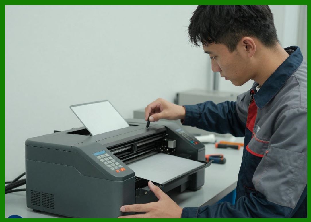
Mechanical flatness also became critical. Uneven printhead pressure across the label width produces incomplete barcode formation in low-pressure regions. |
|
6. Printhead Pressure Systems |
6.1 |
Thermal transfer printing requires precise mechanical pressure between the printhead, ribbon, and label surface. |
6.2 |
Without sufficient pressure, melted ribbon ink cannot bond properly to the label media. Excessive pressure, however, accelerates printhead wear and ribbon damage. |
6.3 |
The printhead assembly is typically spring-loaded against the platen roller. Compression springs provide carefully calibrated force distribution across the print width. |
6.4 |
Pressure uniformity became especially important for wide industrial printers because small variations caused visible print inconsistency. |
6.5 |
Engineers developed floating printhead mechanisms allowing limited self-alignment to compensate for media thickness variations. |
6.6 |
Some industrial systems incorporated adjustable pressure zones, enabling optimization for narrow labels or uneven media types. |
6.7 |
Pressure control directly affects barcode edge sharpness. Excessive pressure can cause ribbon spreading and bar widening, while insufficient pressure produces incomplete transfer. |
6.8 |
Advanced printers later introduced electronically monitored head pressure systems capable of adaptive compensation during operation. |

|
7. Ribbon Motion Synchronization Circuits |
7.1 |
One of the most important differences between direct thermal and thermal transfer printing involves ribbon transport synchronization. |
7.2 |
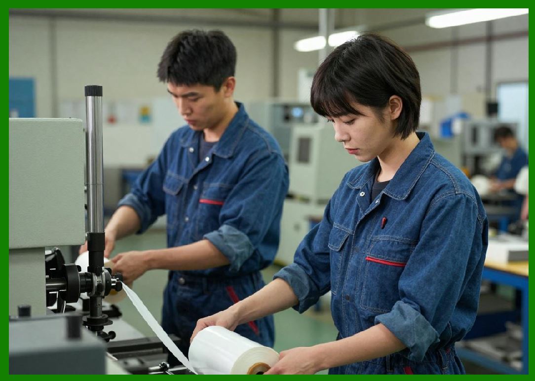
The ribbon and label media must move at precisely matched speeds beneath the printhead. Even minor synchronization errors can cause smearing, wrinkling, image distortion, or ribbon tearing. |
7.3 |
Early ribbon drive systems used mechanically linked transport rollers. Later designs introduced electronically synchronized independent motors. |
7.4 |
Stepper motors became widely used because they provided precise digital motion control. |
7.5 |
Motor synchronization algorithms continuously coordinated: |
1. Label feed speed |
2. Ribbon take-up speed |
3. Ribbon supply tension |
4. Printhead activation timing |

|
7.6 |
Optical encoder systems monitored actual rotational movement and provided real-time feedback to the motion controller. |
7.7 |
The relationship between ribbon speed and media speed must satisfy: |
v_r = v_m |
Where: |
* (v_r) represents ribbon velocity |
* (v_m) represents media velocity |
7.8 |
Maintaining this equality is essential for accurate barcode reproduction. |
|
8. Ribbon Tension Control Systems |
8.1 |
Ribbon tension management became another major engineering challenge in thermal transfer printer design. |
8.2 |
If ribbon tension is too low, wrinkles develop and cause print defects. If tension is too high, ribbon tearing and excessive motor loading occur. |
8.3 |
Early printers used passive friction clutches to regulate ribbon tension. However, passive systems often lacked precision during rapid speed changes. |
8.4 |
More advanced systems introduced active electronic tension control using closed-loop motor regulation. |
8.5 |
Tension sensors monitored ribbon force indirectly through motor current measurements or mechanical displacement sensors. |
8.6 |
Feedback control algorithms dynamically adjusted ribbon motor torque to maintain stable operating conditions. |
8.7 |
Ribbon roll diameter changes during operation because ribbon accumulates onto the take-up spool. Control firmware therefore continuously compensated for changing rotational dynamics. |
8.8 |
Proper tension regulation significantly improved print consistency, barcode sharpness, and ribbon utilization efficiency. |

|
9. Platen Roller Engineering |
9.1 |
The platen roller serves as the mechanical support surface beneath the label media during printing. |
9.2 |
The roller must provide consistent pressure, accurate traction, and dimensional stability across a wide range of environmental conditions. |
9.3 |
Most platen rollers use rubber or elastomer coatings optimized for: |
1. Friction characteristics |
2. Compression properties |
3. Heat resistance |
4. Chemical resistance |
9.4 |
Roller diameter accuracy directly affects vertical print scaling. Even microscopic dimensional variations can distort barcode height or spacing. |
9.5 |
Roller eccentricity introduces periodic motion errors that reduce barcode precision. Therefore, precision machining and balancing became essential. |
9.6 |
The platen roller also influences heat transfer efficiency because it controls contact pressure between media and printhead. |
9.7 |
Wear-resistant coatings extended roller lifespan in industrial high-duty-cycle applications. |

|
10. Electronic Driver Circuits in Thermal Transfer Printers |
10.1 |
Thermal transfer printheads require high-current driver circuits capable of rapidly energizing large arrays of heating elements. |
10.2 |
The driver architecture typically includes: |
1. Serial shift registers |
2. Latch circuits |
3. MOSFET output stages |
4. Current regulation circuits |
5. Thermal protection systems |
10.3 |
Image data is loaded serially into shift registers and then transferred simultaneously into output latches controlling the heating resistors. |

|
10.4 |
Power MOSFETs became dominant because they provide: |
1. Fast switching speed |
2. Low on-resistance |
3. High current capability |
4. Reduced heat dissipation |
10.5 |
The switching speed of driver transistors directly affects print resolution and edge sharpness. |
10.6 |
Current limiting circuits protect printhead elements from overload conditions caused by power supply instability or firmware errors. |
10.7 |
Many systems divided the printhead into multiple independently controlled zones to reduce peak current demand. |
10.8 |
This segmented activation technique became especially important in wide-format industrial barcode printers. |
|
11. Thermal Compensation Algorithms |
11.1 |
Thermal transfer printing requires sophisticated compensation algorithms because print conditions constantly change during operation. |
11.2 |
Several factors influence required heating energy: |
1. Print speed |
2. Ambient temperature |
3. Printhead temperature |
4. Ribbon type |
5. Media composition |
6. Print density |
11.3 |
Firmware continuously monitors operating conditions and dynamically adjusts pulse width, current levels, and print timing. |
11.4 |
Thermal accumulation effects occur during dense printing operations because neighboring pixels influence local temperature. |
11.5 |
Compensation algorithms predict thermal interactions and modify energy delivery accordingly. |
11.6 |
Without compensation, large black areas may become excessively dark while isolated barcode lines appear lighter. |
11.7 |
Advanced printers later incorporated lookup tables and adaptive calibration routines to optimize performance for different ribbon-media combinations. |

|
12. Sensor Systems in Thermal Transfer Printers |
12.1 |
Thermal transfer printers require numerous sensors to monitor operational status and ensure print reliability. |
12.2 |
Important sensor categories include: |
1. Ribbon presence sensors |
2. Ribbon motion sensors |
3. Label gap sensors |
4. Printhead temperature sensors |
5. Head-open sensors |
6. Media-out sensors |
12.3 |
Ribbon sensors often use optical reflective detection methods. Transparent gaps between ribbon sections alter light transmission characteristics. |
12.4 |
Temperature sensors embedded within the printhead provide real-time thermal monitoring. |
12.5 |
Analog sensor outputs typically require amplification, filtering, and analog-to-digital conversion before processor interpretation. |
12.6 |
Sensor fault detection became increasingly important because industrial environments expose electronics to dust, vibration, static electricity, and electromagnetic interference. |
12.7 |
Redundant sensing strategies improved reliability in mission-critical industrial applications. |

|
13. Embedded Firmware Architecture |
13.1 |
Thermal transfer barcode printers depend heavily on embedded firmware for system coordination. |
13.2 |
Firmware responsibilities include: |
1. Barcode encoding |
2. Motion synchronization |
3. Thermal energy management |
4. Sensor monitoring |
5. Communication handling |
6. Error recovery |
7. Ribbon calibration |
13.3 |
Real-time operating constraints became more demanding because thermal transfer printing required precise coordination between multiple moving systems. |
13.4 |
Interrupt-driven firmware architectures allowed rapid response to encoder feedback and sensor events. |
13.5 |
Memory buffering systems stored rasterized image data before print execution. |
13.6 |
Communication protocols gradually evolved to support increasingly complex label formatting commands. |
13.7 |
Modern printer languages originated from these early firmware control systems developed for industrial barcode printing. |

|
14. Advantages of Thermal Transfer Barcode Printing |
14.1 |
Thermal transfer printing provided major advantages that made it the dominant industrial barcode printing technology for many applications. |
14.2 |
Transferred images exhibited excellent durability against abrasion, solvents, ultraviolet exposure, moisture, and temperature extremes. |
14.3 |
The technology supported a wide range of media materials, including: |
1. Paper labels |
2. Polyester films |
3. Polypropylene labels |
4. Vinyl tags |
5. Synthetic industrial labels |
14.4 |
Barcode sharpness and contrast remained highly consistent over long periods. |
14.5 |
Thermal transfer systems enabled permanent asset tracking, laboratory identification, electronics labeling, and outdoor logistics marking. |
14.6 |
The absence of liquid ink systems reduced leakage and contamination problems. |
14.7 |
Industrial reliability improved significantly compared with impact-based technologies. |

|
15. Limitations and Engineering Challenges |
15.1 |
Despite its advantages, thermal transfer printing introduced additional system complexity compared with direct thermal technology. |
15.2 |
Ribbon handling mechanisms increased mechanical complexity and maintenance requirements. |
15.3 |
Ribbon waste became an economic and environmental concern because unused ribbon areas were discarded after printing. |
15.4 |
High printhead friction accelerated wear compared with direct thermal systems. |
15.5 |
Ribbon wrinkles and synchronization errors could produce catastrophic print defects. |
15.6 |
Power consumption remained substantial due to large thermal energy requirements. |
15.7 |
Thermal management became increasingly difficult at high print speeds and wide print widths. |
15.8 |
Nevertheless, the superior durability of thermal transfer labels ensured widespread industrial adoption across numerous sectors. |

|
Technical Content Summary |
This part examined the engineering principles and circuit architecture of thermal transfer barcode printers. The discussion explored ribbon chemistry, thermal energy transfer physics, printhead design, pressure regulation systems, ribbon synchronization circuits, and tension control mechanisms. |
The article described how thermal transfer printers coordinate thermal heating, ribbon movement, and media transport to produce highly durable barcode labels suitable for industrial environments. It also explained the role of MOSFET driver circuits, compensation algorithms, sensor systems, and embedded firmware in maintaining print accuracy and reliability. |
Additionally, this section analyzed the advantages and engineering challenges associated with thermal transfer technology, including superior durability, media flexibility, ribbon management complexity, and thermal control requirements. |
The next part will focus on microprocessor systems and embedded controller architectures inside barcode label printers, including CPU evolution, memory mapping, interrupt systems, DMA controllers, firmware execution models, and real-time printer operating systems. |
 cs@easiersoft.com