Part 5 |
Microprocessor Systems and Embedded Controller Architectures in Barcode Label Printers |
1. Introduction to Embedded Processing in Barcode Printers |
1.1 |
The evolution of barcode label printers from simple electromechanical devices into highly intelligent industrial systems was primarily driven by the development of embedded microprocessor technology. Early barcode printers initially relied on relatively simple logic circuits and discrete timing electronics, but increasing print complexity, barcode standards, communication requirements, and motion control demands quickly exceeded the capabilities of fixed-function hardware. |
1.2 |
Microprocessors transformed barcode printers into programmable embedded computing systems capable of executing sophisticated firmware algorithms. Instead of hardwired logic determining printer behavior, software-controlled architectures enabled dynamic barcode generation, advanced diagnostics, configurable interfaces, downloadable fonts, graphical label composition, and real-time adaptive print control. |
1.3 |
The integration of embedded processors also allowed barcode printers to evolve beyond passive output peripherals. Modern printers became intelligent industrial devices capable of autonomous operation, network communication, local data processing, RFID encoding, security management, and remote diagnostics. |
1.4 |
From an engineering standpoint, barcode printer controller design required balancing several competing constraints: |
1. Real-time performance |
2. Low manufacturing cost |
3. High reliability |
4. Electromagnetic noise tolerance |
5. Industrial environmental durability |
6. Thermal management |
7. Expandability |
1.5 |
Unlike general-purpose computers, barcode printer controllers operate under strict deterministic timing requirements. Motion control, thermal energy delivery, sensor monitoring, and communication handling must remain precisely synchronized to maintain barcode accuracy and prevent print defects. |
|
2. Early Microprocessor Adoption in Barcode Printers |
2.1 |
The first barcode printers using embedded processors emerged during the late 1970s and early 1980s. These systems commonly used 8-bit microprocessors originally developed for industrial control and early personal computers. |
2.2 |
Popular processor families included: |
1. Intel 8080 |
2. Intel 8085 |
3. Zilog Z80 |
4. Motorola 6800 |
5. MOS Technology 6502 |
6. Motorola 6809 |
2.3 |
These processors typically operated at clock frequencies ranging from 1 MHz to 8 MHz. Although primitive by modern standards, they provided sufficient computational capability for barcode encoding, print scheduling, motor control, and communication management. |
|
2.4 |
Most early processors used external support chips for memory management, timing generation, interrupt handling, and peripheral interfacing. System architecture therefore required careful board-level hardware integration. |
2.5 |
Firmware was commonly stored in ROM or EPROM devices, while SRAM chips provided temporary data storage for image buffering and runtime variables. |
2.6 |
The limited memory capacity of early systems strongly influenced printer capabilities. Engineers optimized firmware heavily to minimize code size and memory usage. |
2.7 |
Despite severe hardware limitations, these early embedded controllers established the fundamental architectural principles still used in modern barcode printers. |
|
3. Basic Embedded System Architecture |
3.1 |
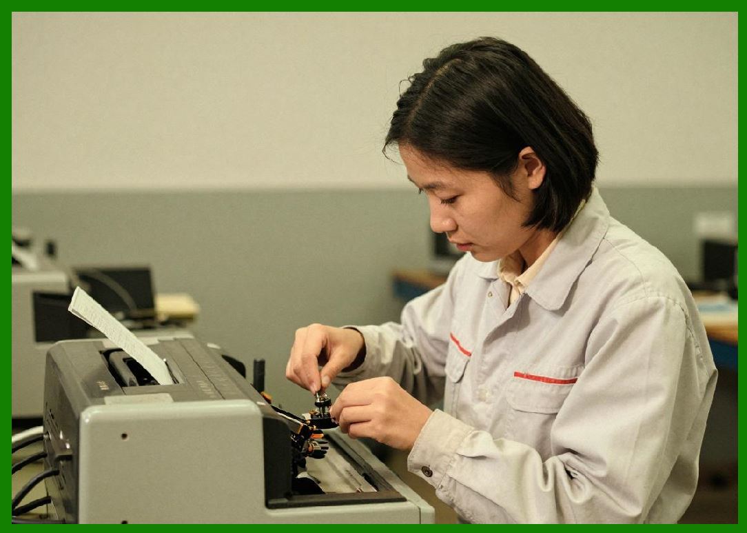
A barcode printer embedded controller typically consists of several interconnected subsystems organized around a central processor. |
3.2 |
The primary architectural components include: |
1. CPU core |
2. Program memory |
3. Data memory |
4. Peripheral interfaces |
5. Timer systems |
6. Interrupt controllers |
7. Communication interfaces |
8. Motor control circuitry |
9. Printhead driver interfaces |
10. Sensor input systems |
|
3.3 |
The CPU executes firmware instructions controlling all printer operations. Program memory stores firmware permanently, while RAM temporarily holds print images, communication buffers, and runtime variables. |
3.4 |
Peripheral interfaces connect the processor to external hardware such as sensors, printheads, motors, keyboards, displays, and network interfaces. |
3.5 |
Timer systems generate precisely controlled timing events essential for synchronization between media movement and printhead activation. |
3.6 |
Interrupt controllers allow external events to temporarily redirect processor execution toward high-priority service routines. |
3.7 |
This architecture enabled barcode printers to coordinate complex real-time operations using relatively simple processors. |
|
4. CPU Clock Generation Circuits |
4.1 |
Stable clock generation became essential for reliable barcode printer operation because print accuracy depended heavily on timing precision. |
4.2 |
Most early systems used quartz crystal oscillators to generate stable reference frequencies. |
4.3 |
The resonant frequency of a quartz crystal follows highly stable piezoelectric oscillation characteristics, providing superior timing accuracy compared with RC oscillators. |
4.4 |
A basic crystal oscillator circuit includes: |
1. Quartz crystal |
2. Inverter amplifier |
3. Feedback resistors |
4. Load capacitors |
4.5 |
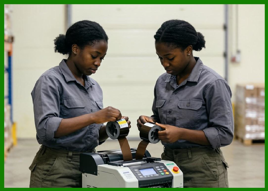
The oscillator generates a periodic clock signal driving the processor and many peripheral subsystems. |
|
4.6 |
Clock stability directly affects: |
1. Print timing precision |
2. Communication baud rates |
3. Motor synchronization |
4. Thermal pulse duration |
5. Sensor sampling accuracy |
4.7 |
Many systems used phase-locked loop (PLL) circuits to multiply or divide clock frequencies for different subsystems. |
4.8 |
Electromagnetic interference shielding around oscillator circuits became important because industrial noise could introduce timing instability. |
|
5. Memory Systems in Barcode Printers |
5.1 |
Memory architecture plays a central role in barcode printer controller design because image generation requires temporary storage of rasterized print data. |
5.2 |
Several memory types are commonly used: |
1. ROM |
2. EPROM |
3. EEPROM |
4. Flash memory |
5. SRAM |
6. DRAM |
5.3 |
Early printers primarily used ROM or EPROM devices for firmware storage. Firmware updates often required physically replacing chips or electrically reprogramming EPROM devices using ultraviolet erasure equipment. |
5.4 |
Static RAM became widely used for image buffering because it provided fast access speed and simple interfacing. |
5.5 |
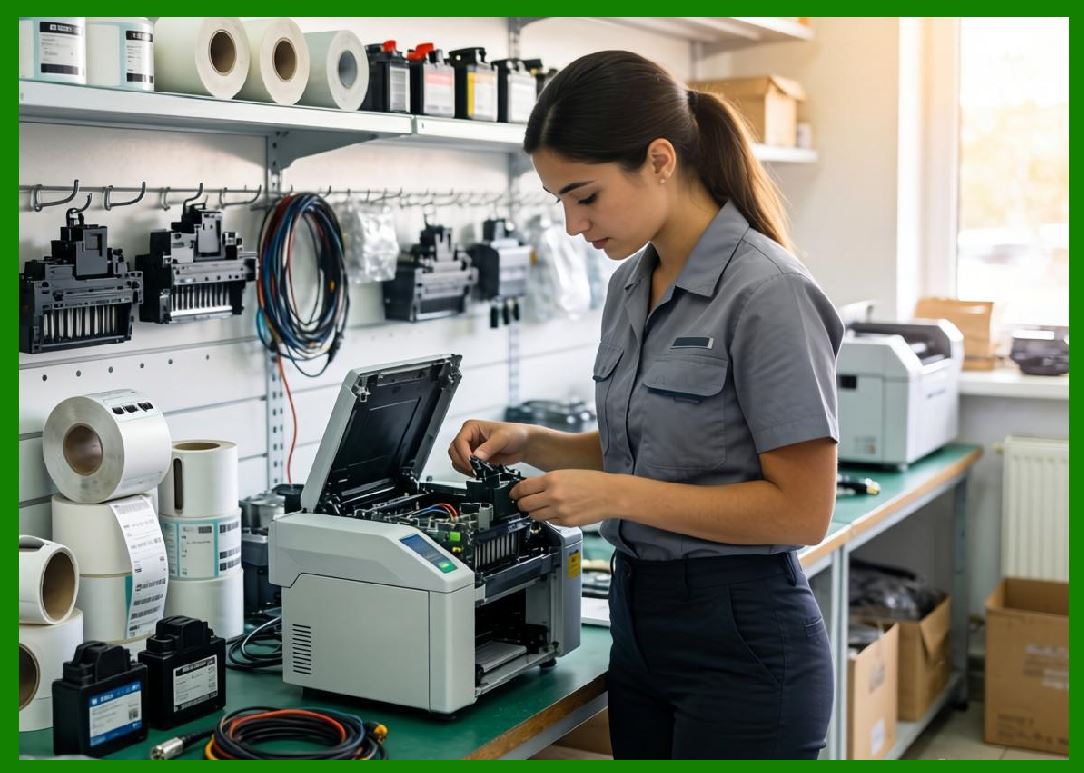
Memory mapping determines how the processor accesses various memory regions and hardware peripherals. |
|
5.6 |
A typical memory map may include: |
1. Boot firmware region |
2. Runtime firmware region |
3. Communication buffers |
4. Print image buffers |
5. Configuration storage |
6. Peripheral registers |
5.7 |
As label complexity increased, memory requirements grew dramatically. High-resolution graphics and scalable fonts demanded far larger image buffers. |
5.8 |
Modern barcode printers now commonly use flash memory and SDRAM systems comparable to embedded industrial computers. |

|
6. Raster Image Buffering Architecture |
6.1 |
Barcode printers generate images using raster-based printing methods. The processor converts barcode data into bitmap representations before transferring them to the printhead. |
6.2 |
Raster image buffering allows the printer to: |
1. Preprocess label images |
2. Optimize print timing |
3. Compensate for thermal behavior |
4. Improve communication efficiency |
6.3 |
Each print line is stored as a sequence of binary pixel values representing heating element activation states. |
6.4 |
Buffer memory size depends on: |
1. Print resolution |
2. Label width |
3. Label length |
4. Graphics complexity |
6.5 |
Double-buffering techniques later became common. One buffer stores incoming data while another feeds the printhead. |
6.6 |
This approach reduces print interruptions and improves throughput. |
6.7 |
DMA systems further improved performance by transferring image data directly between memory and printhead drivers without excessive CPU involvement. |

|
7. Interrupt Systems and Real-Time Processing |
7.1 |
Interrupt systems became critical because barcode printers must respond rapidly to asynchronous hardware events. |
7.2 |
Common interrupt sources include: |
1. Motor encoder pulses |
2. Timer overflows |
3. Communication data arrival |
4. Sensor state changes |
5. Printhead thermal warnings |
6. Ribbon motion events |
7.3 |
When an interrupt occurs, the processor temporarily suspends current execution and jumps to a specialized interrupt service routine (ISR). |
7.4 |
Real-time responsiveness is essential because delayed response can cause: |
1. Barcode distortion |
2. Motion synchronization errors |
3. Data loss |
4. Printhead overheating |
7.5 |
Interrupt priority systems ensure critical events receive immediate attention. |
7.6 |
Timer interrupts often provide the master synchronization mechanism for printing operations. |
7.7 |
Careful ISR optimization became necessary because excessive interrupt latency could destabilize real-time performance. |
|
8. Timer and Counter Circuits |
8.1 |
Timer circuits form the backbone of barcode printer synchronization systems. |
8.2 |
Timers generate precisely controlled intervals used for: |
1. Motor stepping |
2. Thermal pulse timing |
3. Communication baud generation |
4. Sensor sampling |
5. Watchdog monitoring |
8.3 |
Hardware timers operate independently of the main CPU execution flow, improving timing accuracy. |
8.4 |
A timer increments or decrements according to a clock input frequency: |
T = \frac{N}{f} |
Where: |
* (T) represents elapsed time |
* (N) represents timer counts |
* (f) represents clock frequency |
8.5 |
Compare-match timers generate interrupts when counters reach predefined values. |
8.6 |
Pulse-width modulation generation also relies heavily on timer hardware. |
8.7 |
Advanced printers later incorporated multiple independent timer subsystems supporting simultaneous high-speed operations. |
|
9. Input and Output Interface Circuits |
9.1 |
Barcode printer controllers require numerous digital and analog interfaces connecting the processor to external hardware. |
9.2 |
Digital I/O lines commonly control: |
1. Printhead drivers |
2. Motor drivers |
3. LEDs |
4. Buttons |
5. Relays |
6. Cutter mechanisms |
9.3 |
Analog inputs monitor: |
1. Printhead temperature |
2. Power supply voltage |
3. Motor current |
4. Ribbon tension sensors |
9.4 |
Analog-to-digital converters convert sensor voltages into digital values readable by firmware. |
9.5 |
Input protection circuits shield the processor from electrostatic discharge and industrial electrical noise. |
9.6 |
Optoisolators are sometimes used for galvanic isolation between sensitive logic circuits and high-voltage industrial equipment. |
9.7 |
Noise filtering capacitors and Schmitt trigger inputs improve signal reliability. |
|
10. Communication Interface Architecture |
10.1 |
Barcode printers must communicate reliably with host systems such as computers, PLCs, warehouse terminals, and industrial controllers. |
10.2 |
Early communication interfaces included: |
1. RS-232 serial ports |
2. Centronics parallel ports |
3. Current loop interfaces |
4. Proprietary industrial protocols |
10.3 |
RS-232 became especially important because it provided relatively simple long-distance communication capability. |
10.4 |
UART circuits handled asynchronous serial data transmission and reception. |
10.5 |
Baud rate generators derived timing from system clock oscillators. |
10.6 |
Communication firmware managed: |
1. Data framing |
2. Error detection |
3. Flow control |
4. Command parsing |
5. Buffer management |
10.7 |
Later generations introduced USB, Ethernet, Wi-Fi, Bluetooth, and industrial fieldbus protocols. |
|
11. Motor Control Processors and Motion Coordination |
11.1 |
Motion control became increasingly sophisticated as print speeds and resolution improved. |
11.2 |
The processor coordinates multiple simultaneous motion systems including: |
1. Media feed motors |
2. Ribbon motors |
3. Cutter motors |
4. Printhead positioning systems |
11.3 |
Stepper motor control requires carefully timed phase activation sequences. |
11.4 |
Acceleration ramps prevent mechanical resonance and positional instability. |
11.5 |
Closed-loop systems later incorporated encoder feedback for improved accuracy. |
11.6 |
Motion control firmware continuously calculates: |
1. Velocity profiles |
2. Position correction |
3. Torque compensation |
4. Slip detection |
11.7 |
Real-time motion coordination became one of the most processor-intensive aspects of barcode printer operation. |

|
12. Watchdog Circuits and Reliability Engineering |
12.1 |
Industrial barcode printers often operate continuously for long periods in harsh environments. Reliability therefore became a major design priority. |
12.2 |
Watchdog timer circuits monitor processor activity and automatically reset the system if firmware becomes unresponsive. |
12.3 |
A watchdog timer requires periodic refresh signals from firmware. If refresh events stop, the timer assumes system malfunction. |
12.4 |
Electrical noise, firmware bugs, memory corruption, or power instability could otherwise cause system lockups. |
12.5 |
Brownout detection circuits monitor supply voltage and prevent processor operation during unstable power conditions. |
12.6 |
Error-correcting memory techniques gradually emerged in high-end industrial systems. |
12.7 |
Self-diagnostic firmware routines continuously verify sensor functionality, printhead status, and communication integrity. |

|
13. Firmware Execution Models |
13.1 |
Early barcode printers commonly used simple foreground-background firmware architectures. |
13.2 |
The foreground handled time-critical interrupt-driven tasks, while the background executed lower-priority functions such as communication parsing and display updates. |
13.3 |
As printer complexity increased, cooperative multitasking systems emerged. |
13.4 |
Modern printers often use real-time operating systems (RTOS) supporting: |
1. Task scheduling |
2. Memory protection |
3. Interprocess communication |
4. Resource arbitration |
13.5 |
Deterministic execution timing remains essential because barcode printing requires highly predictable synchronization. |
13.6 |
Firmware modularity improved maintainability and feature expansion. |
13.7 |
Network connectivity and remote management further increased software complexity in later generations. |

|
14. Transition to Microcontrollers and System-on-Chip Designs |
14.1 |
As semiconductor integration improved, barcode printers gradually transitioned from discrete processor systems to highly integrated microcontrollers. |
14.2 |
Microcontrollers combined: |
1. CPU cores |
2. RAM |
3. Flash memory |
4. Timers |
5. Communication interfaces |
6. ADCs |
7. PWM generators |
Onto a single integrated circuit. |
14.3 |
This reduced manufacturing cost, board size, and power consumption. |
14.4 |
Integrated peripherals simplified printer electronics design and improved reliability. |
14.5 |
ARM-based architectures later became dominant in high-performance barcode printers. |
14.6 |
Modern System-on-Chip solutions now integrate advanced graphics acceleration, networking, encryption engines, and embedded Linux operating systems. |
14.7 |
Despite enormous increases in computing capability, the fundamental real-time synchronization requirements of barcode printing remain unchanged. |

|
15. The Role of Embedded Intelligence in Modern Barcode Printers |
15.1 |
Modern barcode printers are no longer simple printing devices. They function as intelligent embedded automation platforms. |
15.2 |
Embedded processors now manage: |
1. RFID encoding |
2. Cloud connectivity |
3. Remote diagnostics |
4. Security authentication |
5. Database access |
6. Touchscreen interfaces |
7. Wireless communication |
8. Predictive maintenance |
15.3 |
Artificial intelligence techniques are beginning to appear in advanced industrial print optimization systems. |
15.4 |
Machine learning algorithms may eventually optimize thermal compensation, detect mechanical wear, and predict component failures. |
15.5 |
Edge computing capabilities increasingly allow printers to operate independently within industrial IoT systems. |
15.6 |
The embedded controller has therefore become the central intelligence layer coordinating all aspects of barcode printer functionality. |

|
Technical Content Summary |
This part explored the evolution of microprocessor systems and embedded controller architectures used inside barcode label printers. The discussion examined early 8-bit processor adoption, memory systems, timer circuits, interrupt handling, raster image buffering, communication interfaces, and motion control coordination. |
The article described how embedded firmware transformed barcode printers into programmable real-time systems capable of managing thermal control, barcode encoding, sensor monitoring, and synchronized electromechanical operation. It also analyzed watchdog reliability systems, RTOS architectures, DMA systems, and the transition toward modern ARM-based System-on-Chip platforms. |
Additionally, this section explained how embedded intelligence now enables advanced capabilities such as RFID encoding, wireless networking, remote diagnostics, cloud integration, and predictive maintenance. |
The next part will focus on the detailed design of printhead driver electronics, including MOSFET switching arrays, current regulation circuits, high-speed shift registers, pulse-width modulation systems, thermal protection architectures, and high-current power distribution networks inside barcode label printers. |
 cs@easiersoft.com