Part 7 |
Power Supply Systems in Barcode Label Printers AC Input Stages, Switching Regulators, DC-DC Conversion, Battery Systems, and Industrial Power Reliability Engineering |
1. Introduction to Barcode Printer Power Systems |
1.1 |
The power supply subsystem is one of the most fundamental and technically demanding sections of a barcode label printer. Every major subsystem inside the printer depends on stable electrical power, including the embedded controller, thermal printhead, motors, sensors, communication interfaces, display systems, and optional RFID modules. |
1.2 |
Barcode printers impose unusually difficult electrical load conditions compared with many other embedded devices. During operation, thermal printheads require large bursts of current within extremely short time intervals, while motors and communication circuits simultaneously demand stable regulated voltages. The power system must therefore respond rapidly to changing loads without introducing voltage instability or electrical noise. |
|
1.3 |
Industrial barcode printers are often expected to operate continuously for years in harsh electrical environments containing voltage spikes, electromagnetic interference, brownouts, static discharge, and fluctuating AC mains conditions. Consequently, printer power systems require extensive protection, filtering, and reliability engineering. |
1.4 |
The evolution of barcode printer power architecture closely followed advances in switching regulator technology, semiconductor power devices, magnetic component engineering, and battery systems. Early printers relied primarily on bulky linear transformer supplies, while modern systems use highly efficient switching power architectures with sophisticated digital control algorithms. |
1.5 |
Power subsystem design affects virtually every aspect of printer performance, including: |
1. Print quality |
2. Print speed |
3. Thermal stability |
4. Energy efficiency |
5. Reliability |
6. Electromagnetic compatibility |
7. Portability |
8. System lifespan |

|
2. Fundamental Electrical Requirements of Barcode Printers |
2.1 |
Barcode printers require multiple voltage rails because different subsystems operate at different electrical levels. |
2.2 |
Typical voltage domains include: |
1. Logic supply voltages |
2. Printhead supply voltages |
3. Motor drive voltages |
4. Sensor bias voltages |
5. Communication interface voltages |
6. RF module power supplies |
2.3 |
Early printers commonly used +5V logic systems because TTL integrated circuits dominated embedded electronics during the early development period. |
2.4 |
Motors and thermal printheads usually required higher voltages such as 12V, 24V, or occasionally higher levels depending on printer size and print speed. |
|
2.5 |
The thermal printhead represented the most demanding load because hundreds of resistor elements could activate simultaneously. |
2.6 |
Power consumption varied dramatically according to: |
1. Print density |
2. Print speed |
3. Label width |
4. Ribbon type |
5. Environmental temperature |
2.7 |
A printer producing dense black graphics may consume several times more power than when printing sparse barcode patterns. |
2.8 |
The power system therefore required dynamic regulation capable of handling highly variable transient loads. |
|
3. Early Linear Power Supply Architectures |
3.1 |
The earliest barcode printers commonly used linear transformer-based power supplies because switching regulators were still relatively expensive and less mature. |
3.2 |
A typical linear supply consisted of: |
1. AC input stage |
2. Step-down transformer |
3. Rectifier bridge |
4. Filter capacitors |
5. Linear voltage regulators |
3.3 |
The transformer reduced high-voltage AC mains power to lower AC voltages suitable for printer electronics. |
3.4 |
Rectifier circuits converted alternating current into pulsating direct current using diode bridge networks. |
3.5 |
Large electrolytic capacitors smoothed the rectified voltage by storing energy between AC cycles. |
|
3.6 |
Linear voltage regulators then produced stable output voltages by dissipating excess voltage as heat. |
3.7 |
The output ripple voltage after filtering approximately follows: |
V_r = \frac{I}{fC} |
Where: |
* (V_r) represents ripple voltage |
* (I) represents load current |
* (f) represents ripple frequency |
* (C) represents capacitance |
3.8 |
Although linear supplies offered low electrical noise and simple design, they suffered from poor efficiency and large physical size. |

|
4. Limitations of Linear Power Supplies |
4.1 |
As barcode printers became faster and more compact, the limitations of linear power supplies became increasingly problematic. |
4.2 |
Linear regulators dissipate unused voltage as heat according to: |
P = (V_{in} - V_{out})I |
Where: |
* (P) represents heat dissipation |
* (V_{in}) represents input voltage |
* (V_{out}) represents output voltage |
* (I) represents load current |
4.3 |
High-current thermal printheads therefore generated substantial heat within linear regulator systems. |
4.4 |
Large heat sinks became necessary, increasing printer size and weight. |
4.5 |
Transformer-based supplies also operated inefficiently at varying load levels. |
4.6 |
Heavy iron-core transformers reduced portability and increased manufacturing cost. |
4.7 |
As printhead power requirements increased, switching power supply technology gradually replaced linear architectures in most barcode printers. |

|
5. Introduction to Switching Power Supplies |
5.1 |
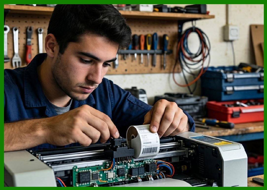
Switching power supplies revolutionized barcode printer design by dramatically improving efficiency, reducing size, and enabling higher power density. |
5.2 |
Unlike linear regulators, switching supplies regulate voltage by rapidly switching semiconductor devices on and off at high frequency. |
5.3 |
Energy is temporarily stored in inductors or transformers and then released to the load in controlled amounts. |
5.4 |
The basic principle of switching regulation relies on duty cycle control: |
V_{out} = DV_{in} |
For ideal buck converter operation. |
Where: |
* (V_{out}) represents output voltage |
* (D) represents duty cycle |
* (V_{in}) represents input voltage |
5.5 |
Switching regulators achieve much higher efficiency because semiconductor switches operate mostly in fully-on or fully-off states, minimizing power dissipation. |
5.6 |
High-frequency operation also allows smaller magnetic components and filter capacitors. |
5.7 |
Modern barcode printers almost universally use switching power architectures. |
|
6. AC Input Stage Design |
6.1 |
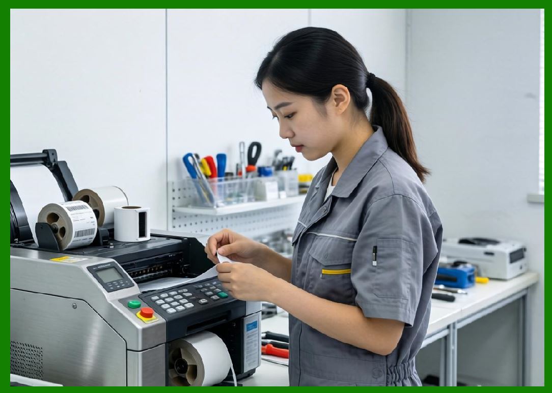
The AC input stage serves as the interface between the barcode printer and the external electrical power grid. |
6.2 |
This section must handle: |
1. Voltage fluctuations |
2. Electromagnetic interference |
3. Surge protection |
4. Safety isolation |
5. Regulatory compliance |
6.3 |
Typical AC input circuitry includes: |
1. Fuse protection |
2. EMI filters |
3. MOV surge suppressors |
4. Common-mode chokes |
5. Rectifier bridges |
6.4 |
EMI filters prevent switching noise generated by the printer from propagating back into the power grid. |
6.5 |
Common-mode chokes suppress high-frequency interference currents. |
6.6 |
MOVs (Metal Oxide Varistors) absorb transient voltage spikes caused by lightning or industrial switching equipment. |
6.7 |
Safety isolation between AC mains and user-accessible circuitry became a critical regulatory requirement. |
6.8 |
International safety standards strongly influenced power supply mechanical and electrical design. |
|
7. Rectification and Bulk Energy Storage |
7.1 |
After AC input filtering, the incoming AC voltage is rectified into DC. |
7.2 |
Bridge rectifiers commonly use four high-current diodes arranged to conduct during both AC half-cycles. |
7.3 |
The resulting pulsating DC waveform is smoothed using bulk electrolytic capacitors. |
7.4 |
Capacitor energy storage helps stabilize voltage during transient load events. |
7.5 |
The stored capacitor energy follows: |
E = \frac{1}{2}CV^2 |
Where: |
* (E) represents stored energy |
* (C) represents capacitance |
* (V) represents voltage |
7.6 |
Large-capacitance bulk storage became especially important because thermal printheads generate sudden high-current pulses. |
7.7 |
Insufficient capacitance can cause voltage droop and visible barcode density variation. |
7.8 |
High-ripple-current capacitors were developed specifically for switching power applications. |

|
8. DC-DC Converter Architectures |
8.1 |
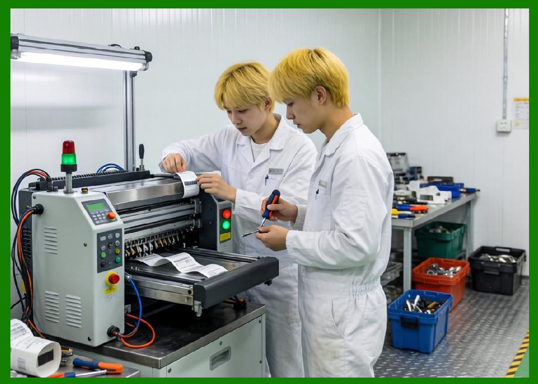
Modern barcode printers commonly use multiple DC-DC converters to generate different voltage rails efficiently. |
8.2 |
Important converter topologies include: |
1. Buck converters |
2. Boost converters |
3. Flyback converters |
4. Forward converters |
5. SEPIC converters |
8.3 |
Buck converters reduce voltage efficiently for logic and processor supplies. |
8.4 |
Boost converters raise voltage when higher printhead drive levels are required. |
8.5 |
Flyback converters provide galvanic isolation between primary and secondary circuits. |
8.6 |
Switching frequency selection strongly affects: |
1. Efficiency |
2. EMI generation |
3. Component size |
4. Thermal performance |
8.7 |
Modern converters often operate between tens of kilohertz and several megahertz. |
|
9. Printhead Power Delivery Systems |
9.1 |
The thermal printhead represents the most power-intensive subsystem in most barcode printers. |
9.2 |
During high-density printing, hundreds of heating elements may activate simultaneously. |
9.3 |
Peak current demand can exceed several amperes in industrial printers. |
9.4 |
The printhead power delivery network must therefore provide: |
1. Low impedance |
2. Fast transient response |
3. Stable voltage regulation |
4. Minimal electrical noise |
9.5 |
Large low-ESR capacitors are often positioned near the printhead driver circuitry. |
9.6 |
Strobe grouping techniques reduce instantaneous current demand by activating printhead sections sequentially. |
9.7 |
Dynamic power management algorithms continuously adjust print timing according to available power capacity. |
9.8 |
Printhead voltage regulation directly affects barcode darkness consistency. |

|
10. Motor Power Systems |
10.1 |
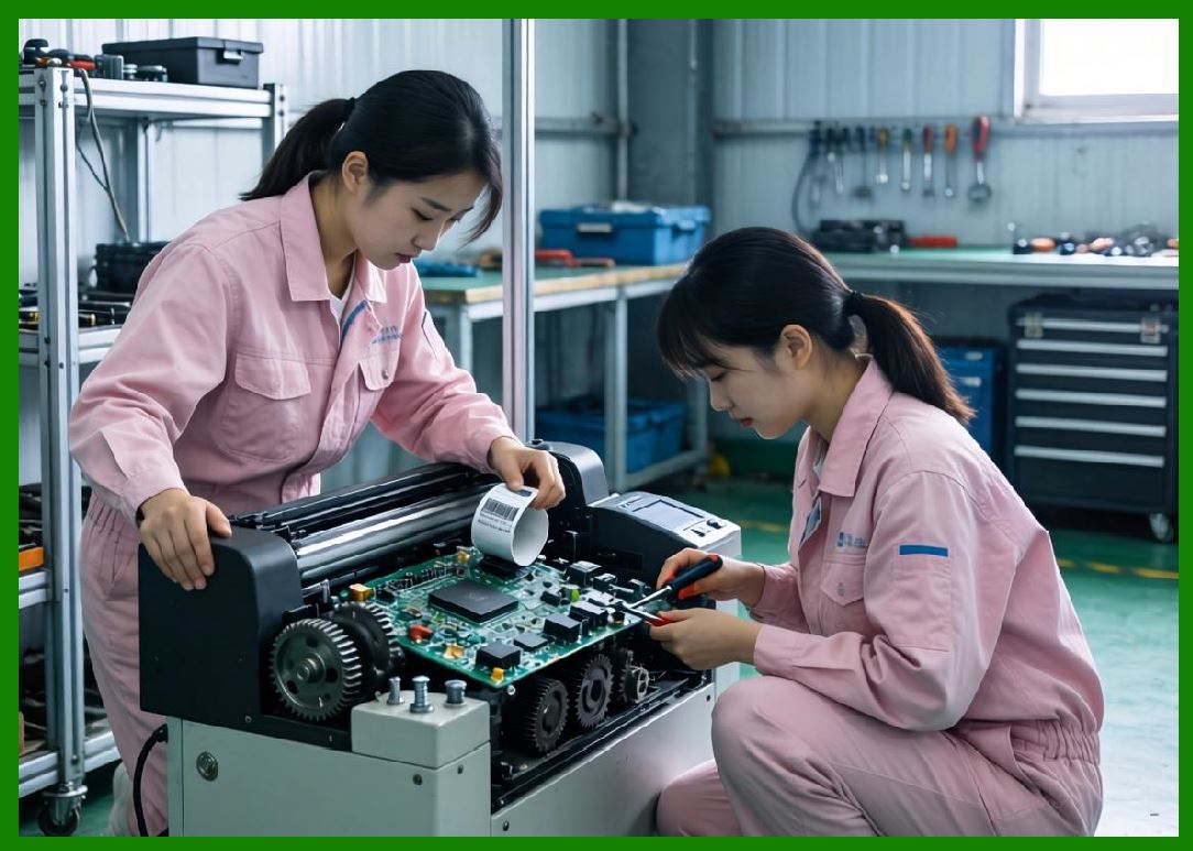
Barcode printers contain multiple motors controlling: |
1. Media feed |
2. Ribbon transport |
3. Cutter mechanisms |
4. Printhead positioning |
10.2 |
Motor loads create additional challenges because startup currents are often substantially higher than steady-state operating currents. |
10.3 |
Motor driver circuits therefore require robust transient current handling capability. |
10.4 |
Brush-type DC motors generate electrical noise due to commutator arcing. |
10.5 |
Snubber circuits and suppression capacitors reduce motor-generated EMI. |
10.6 |
Stepper motors require carefully controlled phase current regulation. |
10.7 |
Microstepping systems use PWM current shaping for smoother motion and reduced vibration. |
10.8 |
Motor supply isolation prevents switching noise from interfering with processor and sensor circuits. |
|
11. Battery Systems in Portable Barcode Printers |
11.1 |
Portable barcode printers introduced entirely new power engineering challenges because they rely on battery operation. |
11.2 |
Battery-powered printers require: |
1. High energy efficiency |
2. Compact size |
3. Thermal management |
4. Intelligent charging systems |
5. Battery protection circuits |
11.3 |
Early portable printers often used nickel-cadmium or nickel-metal hydride battery systems. |
11.4 |
Lithium-ion technology later became dominant due to higher energy density and lower weight. |
11.5 |
Battery management systems monitor: |
1. Voltage |
2. Current |
3. Temperature |
4. Charge state |
5. Cell balancing |
11.6 |
Thermal printing places extremely dynamic demands on batteries because printhead current pulses are highly transient. |
11.7 |
DC-DC boost converters are often required because battery voltage may be lower than required printhead voltage. |
11.8 |
Power optimization firmware dynamically reduces print speed or density during low-battery conditions. |
|
12. Thermal Management in Power Systems |
12.1 |
Power electronics generate significant heat due to semiconductor switching losses, magnetic losses, and conduction resistance. |
12.2 |
Major heat-generating components include: |
1. MOSFETs |
2. Rectifier diodes |
3. Inductors |
4. Transformers |
5. Voltage regulators |
12.3 |
Heat dissipation engineering became increasingly important as printers became smaller and more powerful. |
12.4 |
Thermal resistance modeling helps predict junction temperature rise: |
T_j = T_a + P\theta_{JA} |
Where: |
* (T_j) represents junction temperature |
* (T_a) represents ambient temperature |
* (P) represents power dissipation |
* (\theta_{JA}) represents thermal resistance |
12.5 |
Heat sinks, copper planes, airflow systems, and thermal interface materials improve cooling efficiency. |
12.6 |
Thermal shutdown protection prevents catastrophic power supply failure. |
12.7 |
Long-term reliability strongly depends on maintaining acceptable operating temperatures. |

|
13. Electromagnetic Compatibility (EMC) Engineering |
13.1 |
Switching power supplies generate substantial electromagnetic interference due to rapid voltage and current transitions. |
13.2 |
Poor EMI control can disrupt: |
1. Communication systems |
2. Sensors |
3. Processor timing |
4. RF modules |
5. Nearby industrial equipment |
13.3 |
EMC engineering techniques include: |
1. Shielding |
2. Ground planes |
3. Differential filtering |
4. Controlled PCB layout |
5. Snubber circuits |
6. Ferrite suppression |
13.4 |
PCB trace inductance becomes increasingly important at high switching frequencies. |
13.5 |
Ground loop management prevents noise propagation between subsystems. |
13.6 |
Compliance with FCC, CE, and international EMC regulations became mandatory for commercial products. |

|
14. Protection and Reliability Systems |
14.1 |
Industrial barcode printers often operate in electrically hostile environments. |
14.2 |
Power protection systems guard against: |
1. Overvoltage |
2. Undervoltage |
3. Overcurrent |
4. Thermal overload |
5. Reverse polarity |
6. Electrostatic discharge |
14.3 |
Crowbar circuits and shutdown controllers prevent catastrophic failures. |
14.4 |
Watchdog supervision monitors power sequencing and startup stability. |
14.5 |
Soft-start circuits reduce inrush current during power-on events. |
14.6 |
Transient suppression diodes protect sensitive electronics from voltage spikes. |
14.7 |
Industrial-grade capacitors and high-temperature semiconductors improve long-term reliability. |

|
15. Future Trends in Barcode Printer Power Electronics |
15.1 |
Future barcode printer power systems will continue evolving toward higher efficiency, greater integration, and improved energy intelligence. |
15.2 |
Wide-bandgap semiconductor technologies such as gallium nitride (GaN) and silicon carbide (SiC) will improve switching efficiency and reduce heat generation. |
15.3 |
Digital power management systems will increasingly replace analog control loops. |
15.4 |
Artificial intelligence may optimize energy delivery dynamically according to print workload patterns. |
15.5 |
Wireless charging technologies could eventually appear in portable barcode printers. |
15.6 |
Energy harvesting and ultra-low-power standby systems will become increasingly important in industrial IoT environments. |
15.7 |
Despite these advances, the central challenge remains unchanged: delivering highly stable electrical power to precision thermal printing systems under demanding industrial operating conditions. |

|
Technical Content Summary |
This part explored the detailed design of power supply systems used inside barcode label printers. The discussion examined early linear transformer-based supplies, switching regulator architectures, AC input protection stages, rectification systems, DC-DC converters, and high-current printhead power delivery networks. |
The article described how barcode printers manage complex electrical loads generated by thermal printheads, motors, processors, and communication systems while maintaining voltage stability and electromagnetic compatibility. It also analyzed battery systems for portable printers, thermal management engineering, EMI suppression, reliability protection circuits, and industrial safety requirements. |
Additionally, this section explained how modern power electronics evolved toward highly efficient digitally controlled switching architectures capable of supporting increasingly sophisticated intelligent barcode printer systems. |
The next part will focus on motor control systems and motion synchronization inside barcode label printers, including stepper motors, servo systems, encoder feedback circuits, media transport engineering, ribbon synchronization algorithms, acceleration profiles, and real-time motion control firmware. |
 cs@easiersoft.com