Part 8 |
Motor Control Systems and Motion Synchronization in Barcode Label Printers Stepper Motors, Servo Systems, Encoder Feedback, and Real-Time Motion Control Engineering |
1. Introduction to Motion Control in Barcode Printers |
1.1 |
Motion control systems form the mechanical foundation of barcode label printer operation. No matter how advanced the printhead electronics or embedded firmware may be, barcode quality ultimately depends on precise synchronization between thermal image generation and media movement. Even microscopic positioning errors can distort barcode geometry and reduce scanner readability. |
1.2 |
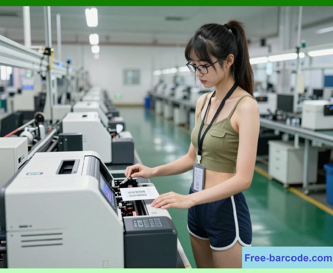
Barcode printers contain multiple coordinated motion subsystems responsible for transporting label media, controlling ribbon movement, positioning printheads, and operating cutters or peel mechanisms. These subsystems must operate with extremely high positional accuracy while maintaining reliable performance under continuous industrial workloads. |
|
1.3 |
The engineering requirements for barcode printer motion systems are unusually demanding because barcode symbologies rely on strict geometric tolerances. Narrow bars, quiet zones, and element spacing must remain dimensionally consistent despite variations in speed, media thickness, friction, temperature, and mechanical wear. |
1.4 |
The evolution of barcode printer motion control closely followed advances in electromechanical engineering, digital motor drivers, encoder systems, microcontrollers, and real-time control algorithms. Early printers relied primarily on open-loop stepper systems, while modern industrial printers increasingly incorporate closed-loop servo architectures and intelligent motion compensation. |
1.5 |
The motion control subsystem directly influences: |
1. Print resolution |
2. Barcode dimensional accuracy |
3. Ribbon alignment |
4. Label registration precision |
5. Print speed capability |
6. Mechanical reliability |
7. Acoustic noise levels |
8. Long-term calibration stability |

|
2. Fundamental Motion Requirements in Barcode Printing |
2.1 |
A barcode printer must coordinate several simultaneous movements during operation. |
2.2 |
The most important motion functions include: |
1. Label media feeding |
2. Ribbon transport |
3. Printhead engagement |
4. Cutter blade operation |
5. Peel mechanism movement |
6. Internal calibration adjustments |
2.3 |
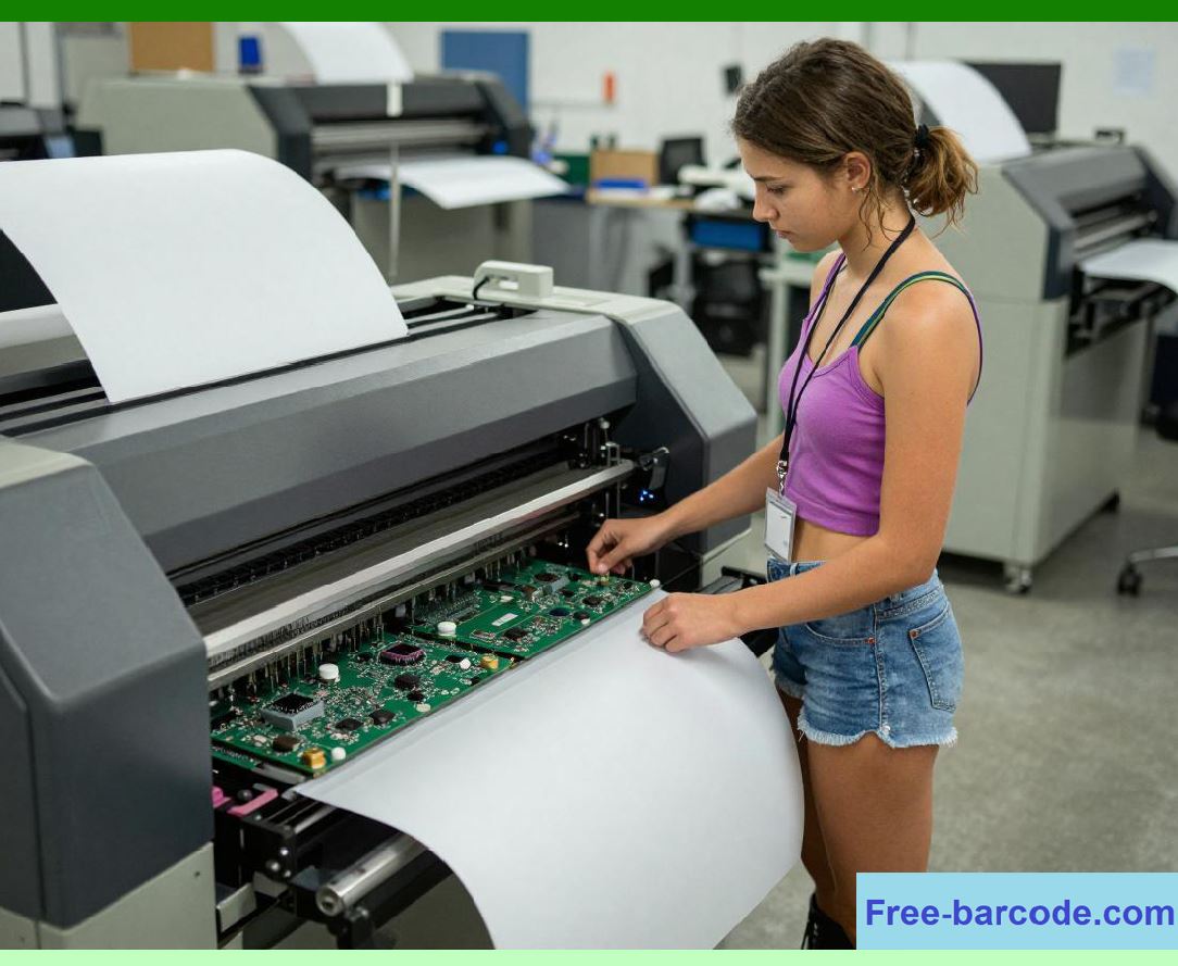
The printhead generates horizontal image lines while the media advances vertically beneath the printhead. |
|
2.4 |
The vertical feed accuracy directly determines print scaling and barcode height consistency. |
2.5 |
The positional relationship between successive print lines must remain extremely stable. |
2.6 |
If media feed distance varies even slightly between print lines, the barcode becomes vertically distorted. |
2.7 |
High-resolution printers therefore require motion increments measured in fractions of a millimeter. |
2.8 |
Motion synchronization must also remain stable across changing load conditions and environmental temperatures. |
|
3. Stepper Motors in Barcode Printers |
3.1 |
Stepper motors became the dominant motion actuator technology in early and mid-generation barcode printers because they provide precise digital position control without requiring complex analog feedback systems. |
3.2 |
A stepper motor rotates in discrete angular increments called steps. |
3.3 |
Each electrical excitation pulse advances the rotor by a fixed angle. |
3.4 |
The total angular displacement follows: |
\theta = n\theta_s |
Where: |
* (\theta) represents total rotation angle |
* (n) represents number of input steps |
* (\theta_s) represents step angle |
3.5 |
Typical step angles include: |
1. 1.8 degrees |
2. 0.9 degrees |
3. 7.5 degrees |
3.6 |
Stepper motors are especially useful in barcode printers because digital pulse counts directly correspond to media movement distance. |
3.7 |
This simplifies synchronization between motion and print timing. |
3.8 |
Stepper systems also provide high holding torque, helping maintain accurate label positioning during printhead engagement. |
|
4. Stepper Motor Electromagnetic Principles |
4.1 |
Stepper motors operate through sequential electromagnetic attraction between stator windings and rotor structures. |
4.2 |
The stator contains multiple phase windings energized in carefully controlled sequences. |
4.3 |
The rotor may use permanent magnets, soft iron teeth, or hybrid structures depending on motor design. |
4.4 |
When a phase winding is energized, magnetic flux aligns the rotor with the energized stator poles. |
4.5 |
Sequential phase excitation causes incremental rotor rotation. |
4.6 |
The electromagnetic torque generated by the motor approximately follows: |
T \propto NI\Phi |
Where: |
* (T) represents torque |
* (N) represents coil turns |
* (I) represents current |
* (\Phi) represents magnetic flux |
4.7 |
Precise phase current control is essential for smooth motion and accurate positioning. |
4.8 |
Stepper motors became highly optimized for barcode printer applications due to their predictable digital behavior. |

|
5. Stepper Motor Driver Circuits |
5.1 |
Stepper motors require specialized driver electronics because the processor cannot directly energize motor windings. |
5.2 |
Driver circuits control current flow through motor phases according to commanded step sequences. |
5.3 |
Common driver architectures include: |
1. Unipolar drivers |
2. Bipolar H-bridge drivers |
3. Chopper current regulators |
4. Microstepping drivers |
5.4 |
Bipolar H-bridge circuits became especially important because they allow current reversal through windings, increasing torque efficiency. |
5.5 |
A typical H-bridge uses four switching transistors controlling bidirectional current flow. |
5.6 |
MOSFET-based H-bridges gradually replaced bipolar transistor designs due to lower conduction losses and faster switching. |
5.7 |
Current regulation circuits prevent excessive winding heating and maintain consistent torque output. |
5.8 |
Stepper driver ICs later integrated current regulation, thermal protection, and microstepping control into compact semiconductor packages. |
|
6. Full-Step, Half-Step, and Microstepping Operation |
6.1 |
Early barcode printers commonly used full-step drive methods because of their simplicity. |
6.2 |
In full-step mode, the motor advances one complete mechanical step for each excitation sequence. |
6.3 |
Half-step operation alternates between single-phase and dual-phase excitation states, doubling effective resolution. |
6.4 |
Microstepping represented a major advancement in motion smoothness and print quality. |
6.5 |
Microstepping uses analog current control to generate intermediate rotor positions between full steps. |
6.6 |
The phase currents are approximately sinusoidal: |
I_A = I_{max}\sin(\theta), \quad I_B = I_{max}\cos(\theta) |
6.7 |
Microstepping reduces: |
1. Mechanical vibration |
2. Acoustic noise |
3. Resonance effects |
4. Positional oscillation |
6.8 |
Smoother motion directly improves barcode edge stability and print consistency. |
|
7. Mechanical Resonance and Vibration Control |
7.1 |
Stepper motors inherently produce periodic torque pulses that can excite mechanical resonance within the printer structure. |
7.2 |
Mechanical resonance causes: |
1. Vibration |
2. Audible noise |
3. Positioning errors |
4. Print distortion |
7.3 |
Resonance becomes especially problematic at specific stepping frequencies. |
7.4 |
Barcode printers therefore require careful acceleration profile design to avoid unstable operating regions. |
7.5 |
Mechanical dampers and elastomer couplings sometimes reduce vibration transmission. |
7.6 |
Microstepping significantly improved resonance suppression. |
7.7 |
Firmware-based anti-resonance algorithms later emerged in advanced industrial printers. |
7.8 |
Stable motion control became increasingly important as print resolution increased. |

|
8. Servo Motor Systems in Advanced Barcode Printers |
8.1 |
Although stepper motors dominated early barcode printers, advanced industrial systems gradually adopted servo motor technology for higher speed and greater precision. |
8.2 |
Servo systems operate using closed-loop feedback control. |
8.3 |
Unlike stepper motors, servo motors continuously monitor actual position using encoder feedback. |
8.4 |
The controller dynamically adjusts motor current to minimize positional error. |
8.5 |
Servo systems offer several advantages: |
1. Higher efficiency |
2. Greater speed |
3. Better torque control |
4. Reduced vibration |
5. Improved dynamic response |
8.6 |
Brushless DC motors became increasingly common in high-performance barcode printers. |
8.7 |
Servo control algorithms often use PID regulation: |
u(t)=K_pe(t)+K_i\int e(t)dt+K_d\frac{de(t)}{dt} |
8.8 |
Closed-loop servo systems improved media synchronization accuracy during high-speed printing. |
|
9. Encoder Feedback Systems |
9.1 |
Encoder systems provide real-time positional feedback for motion control systems. |
9.2 |
Encoders convert mechanical motion into electrical signals readable by the processor. |
9.3 |
Common encoder types include: |
1. Optical encoders |
2. Magnetic encoders |
3. Incremental encoders |
4. Absolute encoders |
9.4 |
Incremental optical encoders became widely used in barcode printers. |
9.5 |
These systems use rotating disks containing transparent and opaque segments. |
9.6 |
Photodetectors generate pulse streams corresponding to rotational movement. |
9.7 |
Quadrature encoder outputs allow direction detection and improved resolution. |
9.8 |
Encoder feedback greatly improves synchronization between media motion and printhead activation timing. |
|
10. Media Transport Mechanisms |
10.1 |
The media transport system physically advances label stock beneath the printhead. |
10.2 |
The primary transport components include: |
1. Platen roller |
2. Drive gears |
3. Feed shafts |
4. Pinch rollers |
5. Media guides |
10.3 |
The platen roller provides traction and pressure against the label media. |
10.4 |
Roller diameter precision directly affects feed accuracy. |
10.5 |
Mechanical backlash within gear systems can introduce positional error. |
10.6 |
Engineers minimized backlash through precision machining and spring-loaded gear assemblies. |
10.7 |
Media guides maintain lateral alignment and prevent skewing. |
10.8 |
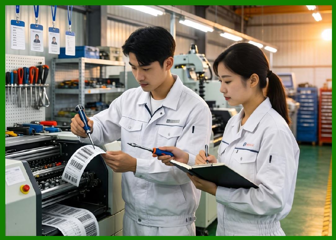
Transport stability strongly influences barcode vertical edge consistency. |
|
11. Ribbon Synchronization Systems |
11.1 |
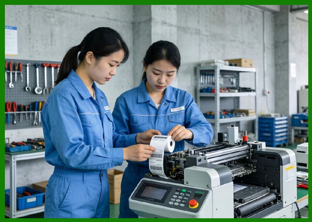
Thermal transfer printers require precise synchronization between ribbon motion and media movement. |
11.2 |
If ribbon velocity differs from media velocity, print defects occur. |
11.3 |
Important synchronization issues include: |
1. Ribbon wrinkling |
2. Smearing |
3. Misregistration |
4. Ribbon tearing |
11.4 |
Dual-motor architectures later enabled independent ribbon and media control. |
11.5 |
Firmware continuously adjusts ribbon motor torque and speed according to encoder feedback. |
11.6 |
Tension regulation systems compensate for changing ribbon spool diameter during operation. |
11.7 |
Adaptive synchronization algorithms improved print consistency across varying print speeds. |
11.8 |
Ribbon control became increasingly sophisticated in wide-format industrial printers. |
|
12. Acceleration and Deceleration Profiles |
12.1 |
Abrupt motor speed changes can produce excessive mechanical stress and positional instability. |
12.2 |
Barcode printer firmware therefore implements controlled acceleration and deceleration profiles. |
12.3 |
Common profile types include: |
1. Linear ramps |
2. Trapezoidal profiles |
3. S-curve acceleration |
12.4 |
Acceleration control reduces: |
1. Gear wear |
2. Belt slippage |
3. Resonance excitation |
4. Motor stalling |
12.5 |
S-curve profiles provide smoother jerk transitions and lower vibration. |
12.6 |
High-speed industrial printers require carefully optimized motion trajectories. |
12.7 |
Firmware calculates acceleration timing dynamically according to label length and print workload. |
12.8 |
Smooth motion directly improves barcode print stability. |
|
13. Sensor Systems for Motion Detection |
13.1 |
Barcode printers contain numerous sensors monitoring media position and motion status. |
13.2 |
Important sensor categories include: |
1. Label gap sensors |
2. Black mark sensors |
3. Ribbon motion sensors |
4. Home position sensors |
5. Media-out sensors |
13.3 |
Optical sensing systems became dominant because they provide high reliability and fast response. |
13.4 |
Infrared LED and phototransistor pairs commonly detect media transitions. |
13.5 |
Sensor signals require analog conditioning circuits including amplification, filtering, and threshold comparison. |
13.6 |
Sensor calibration algorithms compensate for media transparency variations. |
13.7 |
Accurate sensor feedback is essential for label registration precision. |
13.8 |
Industrial contamination resistance became a major design priority for sensor reliability. |

|
14. Real-Time Motion Control Firmware |
14.1 |
Motion control firmware coordinates all electromechanical operations within the barcode printer. |
14.2 |
Important firmware responsibilities include: |
1. Step generation |
2. Encoder interpretation |
3. Velocity regulation |
4. Thermal synchronization |
5. Error recovery |
6. Calibration routines |
14.3 |
Real-time interrupt systems ensure deterministic timing performance. |
14.4 |
Motion algorithms must coordinate precisely with printhead strobe timing. |
14.5 |
Firmware continuously monitors for: |
1. Motor stalls |
2. Media jams |
3. Ribbon slippage |
4. Positioning errors |
14.6 |
Advanced printers later introduced predictive compensation algorithms accounting for mechanical inertia and thermal expansion. |
14.7 |
Modern firmware increasingly resembles industrial CNC motion control systems in complexity. |

|
15. Future Trends in Barcode Printer Motion Systems |
15.1 |
Future barcode printer motion systems will continue evolving toward greater precision, intelligence, and efficiency. |
15.2 |
Closed-loop servo systems will likely become more common even in mid-range printers. |
15.3 |
Advanced digital signal processors may improve real-time motion compensation accuracy. |
15.4 |
Artificial intelligence could dynamically optimize acceleration profiles and wear compensation. |
15.5 |
Magnetic levitation transport systems may eventually appear in specialized ultra-high-speed printers. |
15.6 |
Improved low-noise motor technologies will enhance portable and office-friendly designs. |
15.7 |
Despite future innovations, the fundamental challenge remains unchanged: synchronizing mechanical movement with thermal image generation to maintain precise machine-readable barcode geometry. |

|
Technical Content Summary |
This part explored the detailed engineering principles of motor control systems and motion synchronization inside barcode label printers. The discussion examined stepper motor operation, H-bridge driver circuits, microstepping techniques, resonance suppression, servo control systems, encoder feedback architectures, and media transport mechanics. |
The article described how barcode printers synchronize label movement, ribbon transport, and thermal printhead timing using real-time embedded motion control firmware. It also analyzed acceleration profiles, sensor systems, mechanical vibration management, and high-precision synchronization algorithms necessary for maintaining barcode accuracy. |
Additionally, this section explained the evolution from open-loop stepper systems toward advanced closed-loop servo architectures capable of supporting high-speed industrial barcode printing with improved precision and reliability. |
The next part will focus on sensor technologies and detection systems inside barcode label printers, including optical sensors, transmissive and reflective media detection, ribbon sensing, temperature monitoring circuits, analog signal conditioning, ADC systems, and intelligent calibration algorithms. |
 cs@easiersoft.com