Detailed Explanation of the Principles and Structure of Barcode Printer |
Part 12: Thermal Physics, Heat Transfer Behavior, and Energy Dynamics in Barcode Printing |
1. Introduction to Thermal Physics in Barcode Printing |
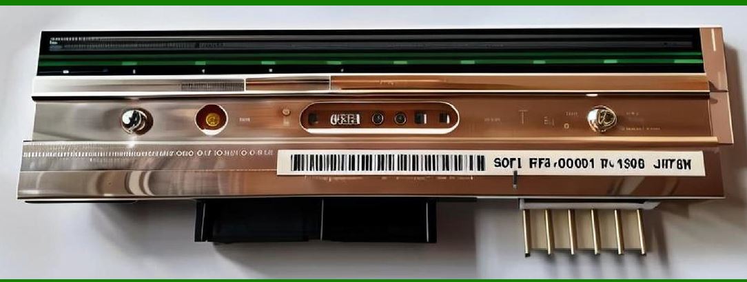
1.1 Thermal physics is at the core of barcode printing technology, especially in thermal and thermal transfer printers. The entire printing process depends on controlled heat generation, precise heat transfer, and rapid thermal response. |
1.2 Unlike mechanical systems that rely on motion alone, barcode printers rely on converting electrical energy into thermal energy at microscopic scales. |
1.3 This thermal energy is then used to either: |
* Directly darken thermal paper (direct thermal printing), or |
* Melt ink from a ribbon onto media (thermal transfer printing) |
|
2. Joule Heating Principle in Print Heads |
2.1 The fundamental physical principle behind thermal print heads is Joule heating, where electrical energy is converted into heat when current passes through a resistive element. |
2.2 The relationship is governed by: |
Q = I^2 R t |
2.3 Where: |
* Q = heat energy generated |
* I = electric current |
* R = electrical resistance of heating element |
* t = time duration of current flow |
2.4 This equation shows that small changes in current or resistance can significantly affect heat output. |

|
3. Micro-Heater Element Structure |
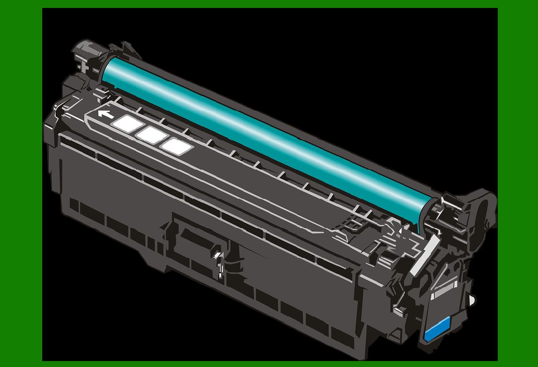
3.1 Each thermal print head contains thousands of micro-heating elements arranged in a precise linear array. |
3.2 These elements are typically made of thin-film resistive materials such as: |
* Tantalum nitride |
* Polysilicon |
* Metal alloy composites |
3.3 Each element is extremely small, often measured in micrometers, allowing high-resolution printing. |
3.4 The elements are individually addressable, enabling pixel-level control of heat generation. |
|
4. Heat Generation and Response Time |
4.1 One of the most critical parameters in barcode printing is thermal response time—the speed at which a heating element reaches its target temperature. |
4.2 Faster response allows: |
* Higher print speeds |
* More precise dot formation |
4.3 The heating and cooling cycles occur in milliseconds or even microseconds. |
4.4 Delayed response can cause: |
* Blurred edges |
* Inconsistent barcode width |

|
5. Heat Transfer Mechanisms |
5.1 Heat transfer in barcode printers occurs through three primary mechanisms: |
* Conduction |
* Convection |
* Radiation (minimal role) |
|
6. Thermal Conduction in Print Heads |
6.1 Conduction is the dominant heat transfer method. |
6.2 Heat flows from the heating element protective layer ribbon or thermal paper. |
6.3 The efficiency of conduction depends on: |
* Material thermal conductivity |
* Contact pressure |
* Surface smoothness |
6.4 Poor conduction leads to uneven printing or weak barcode contrast. |

|
7. Heat Transfer in Direct Thermal Printing |
7.1 In direct thermal printing, heat is transferred directly to chemically coated paper. |
7.2 The coating contains leuco dyes and developers that react to heat. |
7.3 When a threshold temperature is reached: |
* Chemical reaction occurs |
* Color change happens instantly |
7.4 The reaction is irreversible, forming a permanent image. |
|
8. Heat Transfer in Thermal Transfer Printing |
8.1 In thermal transfer systems, heat is used to melt ink from a ribbon. |
8.2 The process involves: |
* Heating ribbon surface |
* Melting ink layer |
* Transferring ink onto media |
8.3 The quality of transfer depends on: |
* Temperature |
* Pressure |
* Dwell time (contact duration) |

|
9. Thermal Inertia and Energy Efficiency |
9.1 Thermal inertia refers to how quickly a system responds to changes in temperature. |
9.2 Low thermal inertia is desirable because it allows: |
* Rapid heating and cooling |
* Precise dot control |
9.3 High inertia leads to: |
* Lag in printing response |
* Smudging or overburning |

|
10. Energy Distribution Across Print Head |
10.1 Energy is not applied uniformly across all heating elements simultaneously. |
10.2 Instead, it is distributed in patterns depending on: |
* Print data |
* Dot density |
* Timing sequences |
10.3 This prevents excessive power draw and overheating. |

|
11. Duty Cycle Control |
11.1 Duty cycle refers to the percentage of time a heating element is active. |
11.2 Controlling duty cycle helps regulate: |
* Heat intensity |
* Energy consumption |
* Print darkness |
11.3 Higher duty cycles produce darker prints but increase thermal stress. |

|
12. Thermal Compensation Mechanisms |
12.1 As the print head heats up during continuous operation, temperature drift can occur. |
12.2 Printers use compensation algorithms to adjust: |
* Pulse duration |
* Current levels |
* Print density |
12.3 This ensures consistent output even during long print jobs. |

|
13. Heat Dissipation and Cooling Behavior |
13.1 After heating, energy must be dissipated quickly to prepare for the next cycle. |
13.2 Cooling occurs through: |
* Conduction into surrounding materials |
* Convection via airflow |
* Heat sinks in industrial models |
13.3 Efficient cooling improves printing speed and component lifespan. |

|
14. Thermal Gradient Effects |
14.1 A thermal gradient occurs when different parts of the print head have different temperatures. |
14.2 This can lead to: |
* Uneven print density |
* Variations in barcode quality |
14.3 Engineers minimize gradients through: |
* Uniform material design |
* Controlled energy distribution |

|
15. Pressure and Heat Interaction |
15.1 Heat alone is not sufficient; mechanical pressure is also required. |
15.2 Pressure ensures: |
* Proper contact between print head and media |
* Efficient heat transfer |
15.3 Insufficient pressure results in weak or incomplete printing. |

|
16. Material Science in Thermal Printing |
16.1 Materials used in thermal systems must withstand: |
* Repeated heating cycles |
* High localized temperatures |
* Mechanical wear |
16.2 Common materials include: |
* Ceramic substrates |
* Protective coatings |
* Heat-resistant polymers |

|
17. Thermal Efficiency Optimization |
17.1 Efficiency is improved by: |
* Reducing thermal losses |
* Enhancing heat concentration |
* Optimizing element spacing |
17.2 High efficiency reduces: |
* Power consumption |
* Heat buildup |

|
18. Environmental Effects on Thermal Behavior |
18.1 External temperature affects thermal response. |
18.2 High ambient temperatures may cause: |
* Overheating |
* Reduced contrast |
18.3 Low temperatures may require higher energy input. |

|
19. Long-Term Thermal Degradation |
19.1 Repeated thermal cycling causes material fatigue. |
19.2 Effects include: |
* Reduced heating efficiency |
* Dead heating elements |
* Protective layer degradation |
19.3 Proper design extends lifespan significantly. |

|
20. Thermal Modeling and Simulation |
20.1 Engineers use thermal simulations to predict behavior. |
20.2 Models include: |
* Heat distribution maps |
* Time-dependent temperature curves |
20.3 Simulation helps optimize: |
* Print head design |
* Energy consumption |

|
21. Future Developments in Thermal Physics for Printing |
21.1 Emerging innovations include: |
* Ultra-low thermal inertia materials |
* Nanostructured heating elements |
* AI-controlled thermal regulation |
21.2 These improvements aim to: |
* Increase speed |
* Reduce energy usage |
* Improve print precision |

|
22. Conclusion of Thermal Physics and Energy Dynamics |
22.1 Thermal physics is the foundation of barcode printing technology. |
22.2 It governs how electrical energy becomes precise, controlled heat patterns. |
22.3 Understanding these principles is essential for optimizing performance, efficiency, and print quality. |
 cs@easiersoft.com