Detailed Explanation of the Principles and Structure of Barcode Printer |
Part 19: Print Head Microstructure, Dot Formation Physics, and Pixel-Level Control Mechanisms |
1. Introduction to Print Head Microstructure |
1.1 The print head is the most critical and technologically advanced component in a barcode printer, responsible for converting electrical signals into precise physical markings on media. |
1.2 At a microscopic level, the print head is not a single continuous surface but an array of thousands of individually controlled heating elements arranged in a straight line. |
1.3 Each of these elements corresponds to a single pot in the printed output, forming the fundamental building block of barcodes and text. |
1.4 The accuracy of this microstructure directly determines barcode readability, resolution, and scanning reliability. |

|
2. Structural Composition of a Thermal Print Head |
2.1 A thermal print head typically consists of multiple layered structures: |
* Substrate layer (ceramic or silicon-based) |
* Resistive heating layer |
* Protective overcoat layer |
* Contact interface layer |
2.2 Each layer serves a specific function: |
* Mechanical support |
* Electrical resistance |
* Heat generation |
* Wear protection |
2.3 The combination of these layers allows repeated high-speed thermal cycling without rapid degradation. |

|
3. Heating Element Array Structure |
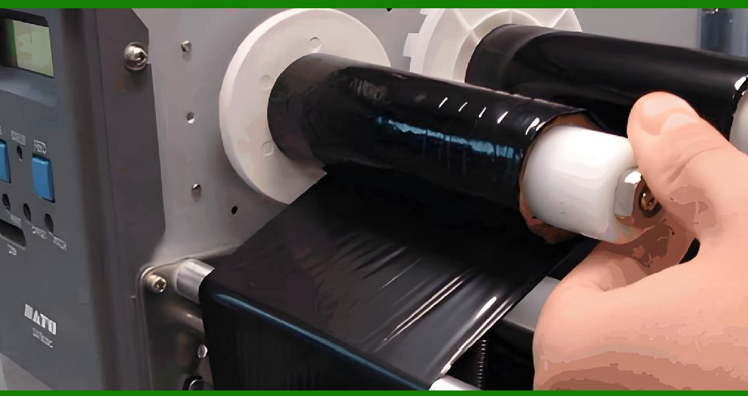
3.1 The heating elements are arranged in a linear array across the width of the print head. |
3.2 Each element is: |
* Electrically independent |
* Thermally responsive |
* Individually addressable |
3.3 The density of these elements determines print resolution, typically measured in dots per inch (dpi). |
3.4 Higher dpi means more heating elements per unit length, resulting in finer detail. |
|
4. Pixel-Level Control Mechanism |
4.1 Each heating element corresponds to one pixel (or partial pixel depending on resolution scaling). |
4.2 The firmware controls each element by sending: |
* Electrical pulse signals |
* Timing instructions |
* Energy levels |
4.3 This allows precise control over: |
* Dot position |
* Dot intensity |
* Dot duration |
4.4 Pixel-level control is what enables barcode precision. |

|
5. Dot Formation Physics |
5.1 Dot formation is the physical process of converting thermal energy into a visible mark. |
5.2 In direct thermal printing: |
* Heat activates chemical coating on paper |
* Reaction produces darkened spot |
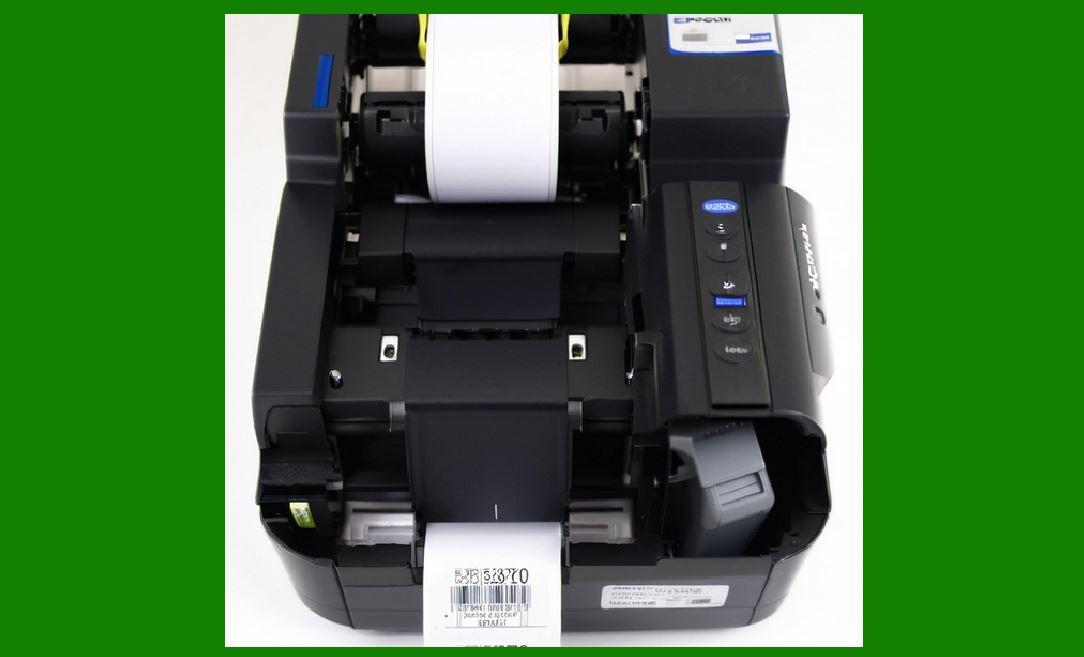
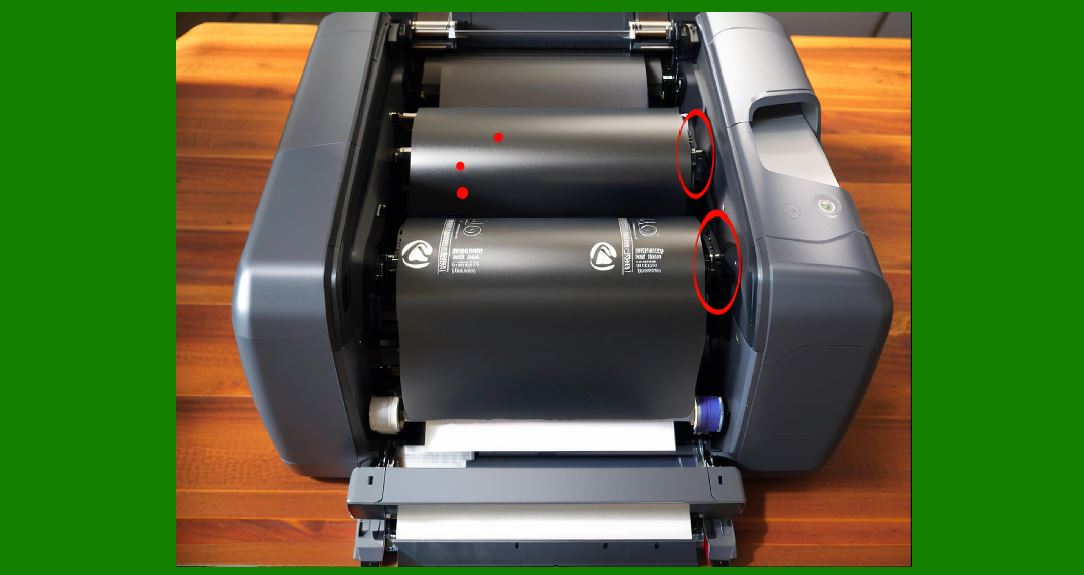
5.3 In thermal transfer printing: |
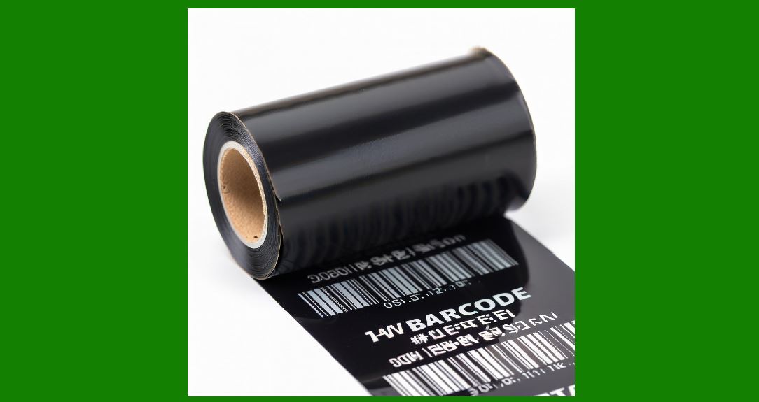
* Heat melts ink from ribbon |
* Ink is transferred to media surface |
5.4 In both cases, a single heating pulse produces a single printed dot. |
|
6. Thermal Energy Concentration and Micro-Heating |
6.1 Each heating element concentrates energy into a very small area. |
6.2 The energy density is extremely high, allowing rapid temperature rise within microseconds. |
6.3 This rapid heating is necessary to achieve: |
* Sharp dot edges |
* High-speed printing capability |
6.4 Cooling occurs almost immediately after the pulse ends. |

|
7. Heat Pulse Timing Control |
7.1 The duration of each heating pulse determines dot darkness and size. |
7.2 This relationship can be conceptually expressed as: |
E \propto I^2 R t |
7.3 Where: |
* E = energy delivered |
* I = current |
* R = resistance |
* t = pulse duration |
7.4 Longer pulses produce darker dots, but excessive duration can cause blurring. |

|
8. Spatial Resolution and Dot Pitch |
8.1 Dot pitch refers to the physical spacing between adjacent heating elements. |
8.2 Smaller dot pitch results in: |
* Higher resolution |
* Smoother curves in 2D barcodes |
* Improved readability |
8.3 However, reducing pitch increases manufacturing complexity. |
|
9. Edge Sharpness and Dot Boundary Formation |
9.1 Edge sharpness is determined by how cleanly each dot transitions from on to off states. |
9.2 Factors affecting edge quality include: |
* Thermal diffusion |
* Material conductivity |
* Pulse precision |
9.3 Poor edge definition leads to barcode scanning errors. |

|
10. Thermal Diffusion Effects |
10.1 Heat does not remain confined to a single element; it spreads to neighboring areas. |
10.2 This phenomenon is called thermal diffusion. |
10.3 Excessive diffusion causes: |
* Blurred dots |
* Overlapping modules in barcodes |
10.4 Engineers minimize diffusion using insulating layers and optimized pulse timing. |
|
11. Dot Size Modulation |
11.1 Dot size can vary depending on energy input and media type. |
11.2 The system adjusts: |
* Pulse width |
* Power level |
11.3 This allows compensation for: |
* Different paper types |
* Environmental conditions |

|
12. High-Density Print Head Challenges |
12.1 High-resolution print heads face challenges such as: |
* Increased heat concentration |
* Crosstalk between adjacent elements |
* Manufacturing precision limits |
12.2 These challenges require advanced material engineering and firmware compensation. |
|
13. Print Head Wear and Degradation |
13.1 Over time, repeated heating cycles cause wear on the protective layer. |
13.2 Effects include: |
* Reduced heating efficiency |
* Missing dots |
* Uneven printing |
13.3 Wear is accelerated by: |
* High-speed printing |
* Abrasive media |

|
14. Compensation for Dead or Faulty Dots |
14.1 Some heating elements may fail over time. |
14.2 Firmware can compensate by: |
* Adjusting neighboring dot intensity |
* Mapping defective elements |
* Using error correction in rendering |
14.3 This helps maintain usable print quality despite partial failure. |

|
15. Thermal Uniformity Across Print Head |
15.1 Uniform heat distribution is essential for consistent output. |
15.2 Uneven heating leads to: |
* Light and dark streaks |
* Inconsistent barcode contrast |
15.3 Thermal calibration ensures uniform performance across all elements. |
|
16. Manufacturing Precision of Print Heads |
16.1 Print head fabrication requires nanometer-level precision. |
16.2 Manufacturing processes include: |
* Thin-film deposition |
* Photolithography |
* Precision etching |
16.3 Any microscopic defect can impact printing performance. |

|
17. Electrical Addressing of Heating Elements |
17.1 Each heating element is connected via a matrix addressing system. |
17.2 This reduces wiring complexity while enabling individual control. |
17.3 The addressing system ensures: |
* Fast activation |
* Minimal signal delay |

|
18. Dynamic Dot Control in Real-Time Printing |
18.1 During printing, dot activation changes dynamically based on data patterns. |
18.2 Firmware must synchronize: |
* Motor movement |
* Dot firing timing |
18.3 This ensures correct spatial alignment. |

|
19. Relationship Between DPI and Barcode Accuracy |
19.1 Higher DPI improves: |
* Edge definition |
* Data density |
* 2D barcode readability |
19.2 However, it also increases: |
* Processing load |
* Energy consumption |
|
20. Future Developments in Print Head Technology |
20.1 Emerging innovations include: |
* Nanomaterial heating elements |
* Self-healing conductive layers |
* Ultra-high DPI microstructures |
20.2 These advancements aim to improve durability, speed, and resolution. |

|
21. Conclusion of Print Head Microstructure and Dot Physics |
21.1 The print head is a highly complex micro-engineered system that operates at the intersection of electronics, materials science, and thermal physics. |
21.2 Its ability to precisely control thousands of microscopic heating elements defines the overall performance of the barcode printer. |
21.3 Understanding dot-level control is essential to understanding how digital data becomes a physical, scannable barcode. |
 cs@easiersoft.com