Detailed Explanation of the Principles and Structure of Barcode Printer |
Part 2: Detailed Structure and Working Mechanism of Thermal Print Heads |
1. Introduction to Thermal Print Head Technology |
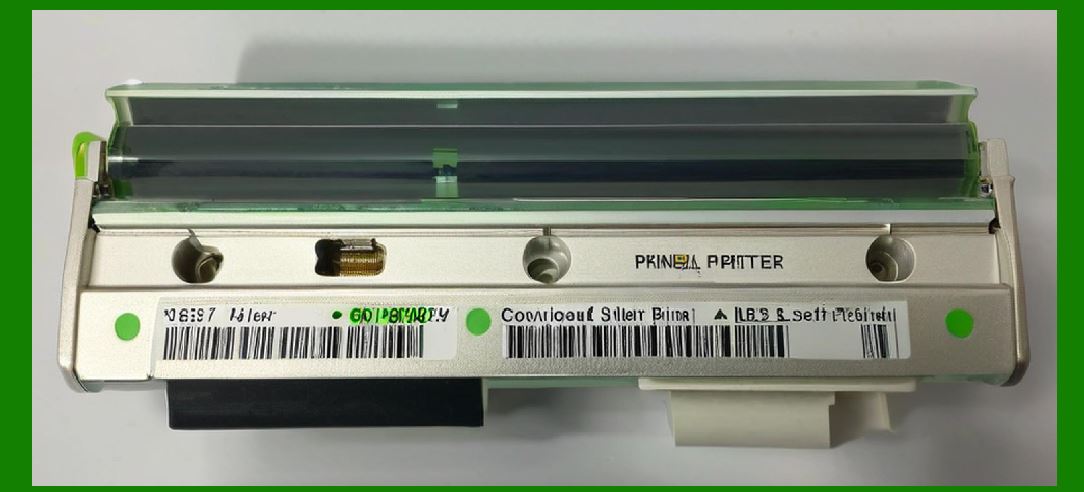
1.1 The thermal print head is the most critical component in a barcode printer, acting as the primary interface between digital instructions and physical output. It is responsible for generating the precise patterns that form barcodes, text, and graphics. |
1.2 In both direct thermal and thermal transfer printers, the print head operates by selectively applying heat to specific (dots) along a linear array. These dots correspond to pixels in the printed image. |
1.3 The accuracy, durability, and efficiency of the thermal print head directly determine the overall performance of the barcode printer. A high-quality print head ensures consistent barcode readability, which is essential for automated scanning systems. |
|
2. Physical Structure of a Thermal Print Head |
2.1 The thermal print head is typically composed of a ceramic or glass substrate that serves as a stable base for mounting heating (elements). This substrate provides mechanical strength and thermal insulation. |
2.2 On the surface of the substrate, a linear array of microscopic resistive heating elements is fabricated using thin-film deposition techniques. These elements are arranged at precise intervals corresponding to the printer resolution, such as 203 dpi, 300 dpi, or 600 dpi. |
2.3 Each heating element is connected to an electrical circuit that allows it to be individually controlled. This enables the printer to activate specific elements while leaving others inactive, forming the desired pattern. |
2.4 A protective coating is applied over the heating elements to shield them from wear, (chemical) damage, and abrasion caused by (contact) with media and ribbon. |
2.5 The print head also includes integrated temperature sensors and sometimes memory chips that store calibration data and usage history. |

|
3. Resolution and Dot Density |
3.1 Resolution in thermal print heads is measured in dots per inch (dpi), indicating how many individual heating elements are present per inch of the print line. |
3.2 Common resolutions include: |
* 203 dpi (8 dots per mm) |
* 300 dpi (12 dots per mm) |
* 600 dpi (24 dots per mm) |
3.3 Higher resolution allows for finer detail and is particularly important for printing small barcodes or high-density 2D codes. |
3.4 The spacing between dots must be extremely precise. Any deviation can result in distorted barcodes that are difficult or impossible to scan. |

|
4. Electrical Operation of Heating Elements |
4.1 Each heating element functions as a (resistor). When an electrical current passes through it, heat is generated due to Joule heating. |
4.2 The amount of heat produced is determined by the equation: |
* Heat CurrentResistance Time |
4.3 The printer control system regulates the current and duration of activation for each element to achieve the desired temperature. |
4.4 Precise timing is crucial. Overheating can damage the print head or media, while insufficient heating can result in faint or incomplete prints. |

|
5. Thermal Printing Process in Direct Thermal Mode |
5.1 In direct thermal printing, the print head applies heat directly to specially coated thermal paper. |
5.2 The coating on the paper contains heat-sensitive chemicals that undergo a color change when exposed to (heat). |
5.3 When a heating element is activated, it causes the corresponding area of the paper to darken, forming a dot. |
5.4 By activating multiple elements in sequence as the paper moves, the printer creates the complete barcode image. |
5.5 This method does not require ink, toner, or ribbon, making it simple and cost-effective. |

|
6. Thermal Transfer Printing Mechanism |
6.1 In thermal transfer printing, a ribbon coated with ink is placed between the print head and the media. |
6.2 The print head heats specific areas of the ribbon, causing the ink to melt and transfer onto the media. |
6.3 The ribbon typically consists of three layers: |
* Base film (usually polyester) |
* Ink layer (wax, resin, or a combination) |
* Protective coating |
6.4 The type of ribbon determines the durability and (resistance) of the printed image. |
6.5 Thermal transfer printing produces more durable labels compared to direct thermal printing, making it suitable for long-term applications. |

|
7. Heat Management and Thermal Control |
7.1 Effective heat management is essential for maintaining print quality and extending the life of the print head. |
7.2 The printer uses algorithms to control the distribution of heat across the print head, preventing overheating in any specific area. |
7.3 Techniques such as pulse-width modulation (PWM) are used to adjust the duration of heating for each element. |
7.4 Cooling occurs naturally through conduction and convection, but some printers also include heat sinks or fans. |
7.5 Temperature sensors provide real-time feedback, allowing the system to adjust operating parameters dynamically. |

|
8. Print Head Wear and Durability |
8.1 The print head is subject to wear (friction) with media and ribbon. |
8.2 (factors) affecting wear include: |
* Media roughness |
* Ribbon (quality) |
* Print speed |
* Temperature settings |
8.3 Over time, the protective coating may degrade, exposing the heating elements and reducing print quality. |
8.4 Regular cleaning and proper maintenance can significantly extend the lifespan of the print head. |

|
9. Alignment and Pressure Mechanisms |
9.1 Proper alignment between the print head and platen roller is critical for uniform pressure distribution. |
9.2 The printer includes adjustable mechanisms to ensure that the print head applies consistent pressure across the entire width of the media. |
9.3 Uneven pressure can result in: |
* Incomplete printing |
* (uneven lines) |
* Barcode distortion |
9.4 (pressure) must be optimized based on media thickness and type. |

|
10. Synchronization with Media Movement |
10.1 The print head operates in synchronization with the movement of the media. |
10.2 Stepper motors control the movement of the platen roller, advancing the media at precise intervals. |
10.3 The timing of heating element activation must match the position of the media to ensure accurate dot placement. |
10.4 Encoders and sensors provide feedback to maintain synchronization. |

|
11. Advanced Features of Modern Thermal Print Heads |
11.1 Modern print heads incorporate advanced features such as: |
* Built-in (memory) for storing configuration data |
* Automatic calibration systems |
* Detection of faulty heating elements |
11.2 Some printers can compensate for damaged elements by adjusting neighboring dots. |
11.3 High-end models support variable (energy) control for different media types. |

|
12. Comparison Between Thin-Film and Thick-Film Technologies |
12.1 Thermal print heads can be manufactured using thin-film or thick-film technology. |
12.2 Thin-film print heads offer: |
* Higher resolution |
* Faster response times |
* Better heat distribution |
12.3 Thick-film print heads are: |
* More durable |
* Less expensive |
* Suitable for lower-resolution applications |
12.4 The choice depends on the application requirements and cost considerations. |

|
13. Role of Print Head in Barcode Accuracy |
13.1 The precision of the print head directly affects barcode accuracy. |
13.2 Parameters such as bar width, edge sharpness, and spacing must be controlled within tight tolerances. |
13.3 Even minor deviations can lead to scanning failures, especially in high-density codes. |
13.4 Quality assurance processes often include verification of printed barcodes using specialized scanners. |

|
14. Maintenance and Cleaning Procedures |
14.1 Regular cleaning of the print head is essential to remove dust, adhesive residue, and ink buildup. |
14.2 Cleaning is typically performed using: |
* Isopropyl alcohol |
* Lint-free wipes |
14.3 The printer should be powered off and cooled before cleaning to avoid damage. |
14.4 Preventive maintenance schedules help ensure consistent performance. |

|
15. Common Failure Modes |
15.1 Common issues with thermal print heads include: |
* Dead pixels (non-functional heating elements) |
* Uneven heating |
* Physical damage (impact) |
15.2 Symptoms of failure include: |
* Missing (lines) |
* Faded prints |
* Inconsistent barcode quality |
15.3 Early detection and replacement are crucial to avoid operational disruptions. |

|
16. Innovations in Thermal Print Head Design |
16.1 Recent innovations focus on improving efficiency, durability, and print quality. |
16.2 Developments include: |
* Nano-coatings for enhanced wear resistance |
* Improved thermal (distribution) |
* Integration with smart diagnostics systems |
16.3 These advancements contribute to longer lifespan and reduced maintenance costs. |

|
17. Interaction with Firmware and Control Systems |
17.1 The print head does not operate independently; it is controlled by firmware that determines which elements to activate and when. |
17.2 The firmware uses algorithms to optimize print quality based on: |
* Media type |
* Print speed |
* Environmental conditions |
17.3 Communication between the control board and print head is achieved through high-speed electrical interfaces. |

|
18. Conclusion of Thermal Print Head Mechanism |
18.1 The thermal print head is the heart of a barcode printer, translating digital instructions into precise physical patterns. |
18.2 Its design involves a complex interplay of materials science, electrical engineering, and thermal physics. |
18.3 Understanding its structure and operation is essential for optimizing barcode printing performance and ensuring reliable data capture. |
 cs@easiersoft.com