Historical Development of Barcode Printing Technology (Part 10) |
*(Focus: Signal Processing in Barcode Verification, Optical Scanning Physics, Decoding Algorithms, and Error Correction Mechanisms)* |
72. Introduction to Barcode Reading and Verification Systems |
72.1 |
While barcode printing is critical, its ultimate success depends on accurate detection and decoding by scanning systems. A perfectly printed barcode that cannot be reliably scanned is operationally useless. Therefore, barcode printing technology has always evolved alongside optical scanning and signal processing technologies. |
72.2 |
This section explores the technical foundations of how printed barcodes are: |
72.2.1 |
Illuminated and optically captured |
72.2.2 |
Converted into electrical signals |
72.2.3 |
Processed into digital data |
72.2.4 |
Validated using error detection and correction mechanisms |
72.3 |
Understanding these processes is essential because printing quality directly influences signal quality, which in turn affects decoding reliability. |

|
73. Optical Principles of Barcode Scanning |
73.1 Light Reflection and Absorption |
73.1.1 |
Barcode scanning is based on the principle of contrast in light reflectance. |
73.1.2 |
Dark bars absorb light, while light spaces reflect it. |
73.1.3 |
When illuminated, the barcode produces a pattern of reflected (light) intensity corresponding to its structure. |
73.2 Illumination Sources |
73.2.1 |
Different types of light sources are used in scanners: |
73.2.1.1 |
Laser diodes (traditional scanners) |
73.2.1.2 |
Light-emitting diodes (LEDs) |
73.2.1.3 |
Imaging sensors (camera-based systems) |
73.2.2 |
Each has advantages in terms of: |
73.2.2.1 |
Depth of field |
73.2.2.2 |
Scanning speed |
73.2.2.3 |
Resolution |
73.3 Optical Sensors |
73.3.1 |
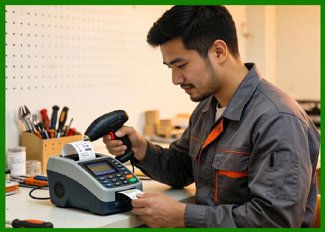
Sensors detect reflected light and convert it into electrical signals. |
73.3.2 |
Common sensor types include: |
73.3.2.1 |
Photodiodes |
73.3.2.2 |
Charge-coupled devices (CCD) |
73.3.2.3 |
CMOS image sensors |
73.3.3 |
Modern systems increasingly use imaging sensors for flexibility and accuracy. |
|
74. Signal Acquisition and Analog Processing |
74.1 Conversion of Light to Electrical Signals |
74.1.1 |
Reflected light intensity is converted into an analog electrical signal. |
74.1.2 |
The signal waveform represents the pattern of bars and spaces. |
74.2 Signal Amplification |
74.2.1 |
The raw signal is often weak and requires amplification. |
74.2.2 |
Amplifiers increase signal strength while minimizing noise. |
74.3 Noise Sources in Signal Acquisition |
74.3.1 |
Noise can arise from: |
74.3.1.1 |
Ambient light |
74.3.1.2 |
Sensor (electronics) |
74.3.1.3 |
Surface irregularities |
74.3.2 |
Noise reduces signal clarity and affects decoding accuracy. |
74.4 Analog Filtering |
74.4.1 |
Filters are used to remove unwanted noise. |
74.4.2 |
Common techniques include: |
74.4.2.1 |
Low-pass filtering |
74.4.2.2 |
Band-pass filtering |
|
75. Digital Signal Processing (DSP) |
75.1 Analog-to-Digital Conversion |
75.1.1 |
The analog signal is converted into a digital format. |
75.1.2 |
Sampling rate must be high enough to capture fine (details). |
75.2 Edge Detection |
75.2.1 |
DSP algorithms identify transitions between bars and spaces. |
75.2.2 |
Accurate edge detection is critical for determining bar widths. |
75.3 Thresholding Techniques |
75.3.1 |
Thresholding converts grayscale signals into binary patterns. |
75.3.2 |
Adaptive thresholding adjusts based on signal conditions. |
75.4 Signal Normalization |
75.4.1 |
Normalization compensates for variations in brightness and contrast. |
75.4.2 |
This ensures consistent decoding across different environments. |

|
76. Decoding Algorithms for Linear Barcodes |
76.1 Bar Width Measurement |
76.1.1 |
Linear barcode decoding relies on measuring widths of bars and spaces. |
76.1.2 |
These measurements are compared against known encoding patterns. |
76.2 Pattern Recognition |
76.2.1 |
Each barcode symbology has defined patterns. |
76.2.2 |
The decoder matches measured patterns to valid sequences. |
76.3 Start/Stop Detection |
76.3.1 |
Special patterns indicate the beginning and end of the barcode. |
76.3.2 |
These markers help synchronize decoding. |
76.4 Checksum Validation |
76.4.1 |
Most linear barcodes include a checksum digit. |
76.4.2 |
This is used to verify data integrity. |
|
77. Decoding Algorithms for Two-Dimensional Barcodes |
77.1 Image-Based Decoding |
77.1.1 |
2D barcodes are decoded using image processing techniques. |
77.1.2 |
The entire symbol is captured as an image. |
77.2 Grid Detection and Alignment |
77.2.1 |
The decoder identifies the grid structure of the barcode. |
77.2.2 |
Alignment patterns are used to correct orientation and distortion. |
77.3 Data Extraction |
77.3.1 |
Data is extracted from individual modules (cells). |
77.3.2 |
Each module represents a binary value. |
77.4 Example: QR Code Decoding |
77.4.1 |
QR Code decoding involves: |
77.4.1.1 |
Detection of finder patterns |
77.4.1.2 |
Perspective correction |
77.4.1.3 |
Data region extraction |
77.4.1.4 |
Error correction processing |

|
78. Error Detection and Correction Mechanisms |
78.1 Importance of Error Handling |
78.1.1 |
Printed barcodes are subject to damage and distortion. |
78.1.2 |
Error handling ensures data can still be recovered. |
78.2 Checksum Techniques in Linear Barcodes |
78.2.1 |
Checksums detect errors in data. |
78.2.2 |
Common methods include: |
78.2.2.1 |
Modulo-10 algorithms |
78.2.2.2 |
Weighted sums |
78.3 Reed-Solomon Error Correction |
78.3.1 |
2D barcodes often use Reed-Solomon algorithms. |
78.3.2 |
This allows recovery of missing or damaged data. |
78.3.3 |
Used in: |
78.3.3.1 |
QR Code |
78.3.3.2 |
Data Matrix |
78.4 Error Tolerance Levels |
78.4.1 |
Error correction levels determine how much damage can be tolerated. |
78.4.2 |
Higher levels increase robustness but reduce data capacity. |

|
79. Interaction Between Printing Quality and Scanning Performance |
79.1 Impact of Print Defects on Signal Quality |
79.1.1 |
Print defects such as: |
79.1.1.1 |
Blurred edges |
79.1.1.2 |
Low contrast |
79.1.1.3 |
Missing elements |
79.1.2 |
Directly degrade signal quality. |
79.2 Tolerance of Modern Scanners |
79.2.1 |
Modern scanners are more tolerant of imperfections. |
79.2.2 |
However, excessive defects still cause failures. |
79.3 Optimization Strategies |
79.3.1 |
To ensure reliable scanning: |
79.3.1.1 |
Maintain high print quality |
79.3.1.2 |
Use appropriate materials |
79.3.1.3 |
Perform regular verification |

|
80. Advanced Developments in Barcode Decoding |
80.1 AI-Based Decoding Systems |
80.1.1 |
Artificial intelligence improves decoding accuracy. |
80.1.2 |
AI can handle: |
80.1.2.1 |
Distorted images |
80.1.2.2 |
Low-quality prints |
80.2 Multi-Spectral Imaging |
80.2.1 |
Uses multiple wavelengths of light. |
80.2.2 |
Enhances detection under challenging conditions. |
80.3 3D Surface Scanning |
80.3.1 |
Used for barcodes printed on curved or uneven surfaces. |

|
81. Summary of Part 10 |
81.1 |
Barcode scanning relies on optical principles and signal processing. |
81.2 |
Accurate decoding depends on high-quality signal acquisition. |
81.3 |
Digital signal processing converts optical data into usable information. |
81.4 |
Error detection and correction mechanisms ensure reliability. |
81.5 |
Printing quality and scanning performance are closely interconnected. |
81.6 |
Advanced technologies such as AI and multi-spectral imaging are enhancing decoding capabilities. |

|
Next Step |
* Firmware architecture of barcode printers |
* Command language execution pipelines |
* Memory management and data buffering |
* Real-time operating systems in printers |
 cs@easiersoft.com