Part 15: Detailed Explanation of Printer Firmware Hardware Control Layer (Printhead, Motors, Sensors, and Timing Coordination) |
1. Introduction to Hardware Control in Printer Firmware |
In printer systems supporting Page Description Languages and command languages such as: |
1. ZPL |
2. EPL |
3. PCL |
4. PostScript |
5. TSPL |
6. DPL |
7. SBPL |
8. CPCL |
the firmware does not only interpret commands and render images - it also directly controls physical hardware components. |

|
These include: |
* Thermal printheads |
* Stepper motors |
* Media sensors |
* Ribbon sensors (for thermal transfer printers) |
* Temperature sensors |
* Cover open sensors |
* Encoder wheels |
* Cutter mechanisms |
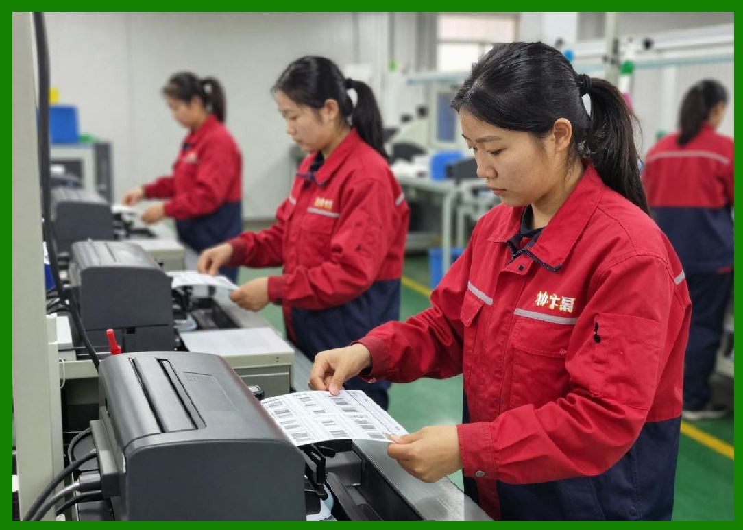
This hardware control layer is what transforms digital raster data into physical inkless thermal marks or printed labels. |
This part explains how firmware synchronizes hardware-level execution with real-time raster output. |
|
2. Printer Hardware Control Architecture Overview |
Printer firmware is typically divided into layers: |
1. Communication layer |
2. Command interpreter |
3. Raster image processor (RIP) |
4. Hardware abstraction layer (HAL) |
5. Device driver layer |
6. Real-time control loop |
The hardware control layer (HAL + drivers) is responsible for translating logical print instructions into electrical signals. |

|
3. Core Hardware Components in Printers |
3.1 Thermal Printhead |
The printhead is the core output device. |
It contains: |
* Hundreds or thousands of heating elements |
* Arranged in a linear array |
* Controlled in microsecond timing |
Each dot corresponds to: |
* 1 heating element |
* 1 bit in raster data |
3.2 Stepper Motor System |
Stepper motors control media movement. |
Functions: |
* Feed labels forward |
* Maintain precise dot alignment |
* Synchronize with printhead firing |

|
3.3 Media Sensors |
Detect label position. |
Types: |
* Gap sensors |
* Black mark sensors |
* Reflective optical sensors |
3.4 Temperature Sensors |
Monitor printhead heat. |
Used to: |
* Prevent overheating |
* Adjust print density |
3.5 Cutter Mechanism (Optional) |
Used in industrial printers to cut labels automatically. |
|
4. Hardware Abstraction Layer (HAL) |
The HAL isolates firmware logic from hardware specifics. |
4.1 Purpose of HAL |
* Hardware independence |
* Driver reuse |
* Simplified firmware design |
4.2 HAL Responsibilities |
1. Printhead control |
2. Motor stepping |
3. Sensor reading |
4. Timing synchronization |
4.3 Device Driver Layer |
Drivers translate HAL commands into electrical signals. |

|
5. Printhead Control System |
The printhead is the most timing-sensitive component. |
5.1 Dot Activation Model |
Each dot is controlled as: |
* ON heat applied |
* OFF no heat |
5.2 Printhead Strobe Signals |
Firmware sends: |
* Strobe pulses |
* Latch signals |
* Data shift registers |
5.3 Serial Data Loading |
Raster data is shifted into printhead registers bit-by-bit. |
5.4 Energy Control |
Heating elements require controlled energy pulses. |

|
6. Printhead Timing Synchronization |
Timing is critical. |
6.1 Dot Clock System |
Each clock cycle represents: |
* One column of print dots |
6.2 Latch Timing |
After shifting data: |
* Data is latched |
* Heating occurs simultaneously |
6.3 Microsecond Precision |
Modern printers operate at microsecond-level precision. |
6.4 Thermal Stabilization Delays |
Firmware accounts for heat accumulation. |

|
7. Stepper Motor Control System |
Motors move media precisely. |
7.1 Step Sequence Control |
Motors move in discrete steps: |
* Step pulse movement increment |
7.2 Microstepping (Advanced Systems) |
Improves smoothness and accuracy. |
7.3 Acceleration Profiles |
Firmware uses: |
* Ramp-up speed |
* Constant speed |
* Ramp-down speed |
7.4 Synchronization with Printhead |
Motor movement must match raster output timing. |

|
8. Closed-Loop Motor Control |
Some printers use feedback systems. |
8.1 Encoder Feedback |
Tracks actual movement. |
8.2 Error Correction |
Firmware adjusts for drift. |
8.3 Position Verification |
Ensures label alignment accuracy. |
|
9. Media Sensor Integration |
Sensors ensure correct label positioning. |
9.1 Gap Detection |
Detects spacing between labels. |
9.2 Black Mark Detection |
Detects printed marks on media backing. |
9.3 Continuous Media Detection |
Used for roll-fed media. |
9.4 Sensor Calibration |
Firmware calibrates sensor thresholds dynamically. |

|
10. Real-Time Sensor Event Handling |
Sensor input triggers firmware actions. |
10.1 Interrupt-Based Detection |
Sensors trigger interrupts instantly. |
10.2 Event Classification |
Events include: |
* Media present |
* Media out |
* Head open |
10.3 Safety Responses |
Critical events may halt printing. |

|
11. Thermal Control System |
Heat management is essential. |
11.1 Printhead Temperature Monitoring |
Temperature sensors continuously monitored. |
11.2 Dynamic Power Adjustment |
Firmware reduces heating when needed. |
11.3 Thermal Compensation Algorithms |
Adjust print density based on heat. |
11.4 Overheat Protection |
Automatic shutdown if unsafe. |

|
12. Print Energy Distribution Control |
Heating must be carefully balanced. |
12.1 Dot Energy Control |
Each dot receives precise energy. |
12.2 Print Density Adjustment |
Firmware modifies heating intensity. |
12.3 Darkness Settings |
User-configurable print darkness levels. |
|
13. Print Timing Coordination Model |
All hardware components must synchronize. |
13.1 Master Clock System |
Central timing reference. |
13.2 Subsystem Synchronization |
Motors and printhead must align perfectly. |
13.3 Jitter Control |
Timing fluctuations minimized. |

|
14. Raster-to-Hardware Pipeline |
Raster data is directly mapped to hardware signals. |
14.1 Scanline Output Flow |
Each scanline: |
1. Rendered |
2. Transferred |
3. Printed |
14.2 Data Shift Pipeline |
Bits shift into printhead registers. |
14.3 Latching and Firing |
All dots fire simultaneously per line. |

|
15. Cutter Control System (If Present) |
Industrial printers may include cutters. |
15.1 Cutter Activation Timing |
Triggered after label completion. |
15.2 Safety Interlocks |
Prevents cutting during movement. |
15.3 Partial Cut Modes |
Some systems support half-cut or perforation. |

|
16. Hardware Error Detection Systems |
Firmware constantly monitors hardware. |
16.1 Printhead Fault Detection |
Detects open or short circuits. |
16.2 Motor Stall Detection |
Detects movement failure. |
16.3 Sensor Failure Detection |
Detects missing or invalid signals. |

|
17. Emergency Shutdown Mechanisms |
Critical safety systems exist. |
17.1 Immediate Power Cut |
Stops all hardware activity. |
17.2 Safe State Entry |
Ensures hardware stability. |
17.3 Error Logging |
Stores failure data in memory. |
|
18. Hardware Calibration Systems |
Printers require calibration. |
18.1 Printhead Alignment Calibration |
Ensures dot accuracy. |
18.2 Sensor Calibration |
Adjusts detection thresholds. |
18.3 Motor Step Calibration |
Ensures accurate movement distance. |

|
19. Hardware-Firmware Communication Bus |
Internal communication system includes: |
19.1 SPI Interfaces |
Used for high-speed device control. |
19.2 I2C Interfaces |
Used for sensors and control chips. |
19.3 GPIO Control |
Direct hardware signaling. |
19.4 Parallel Data Lines |
Used for printhead data transfer. |

|
20. Real-Time Hardware Scheduling |
Hardware operations are tightly scheduled. |
20.1 Execution Windows |
Each component has defined timing slots. |
20.2 Priority Hardware Tasks |
Printhead > motors > sensors > background tasks |
20.3 Deterministic Hardware Behavior |
Ensures repeatable output. |
|
21. Power Management in Hardware Control |
Firmware manages energy usage. |
21.1 Idle State Reduction |
Reduces heating when inactive. |
21.2 Sleep Mode Hardware Shutdown |
Non-critical hardware disabled. |
21.3 Wake-Up Sequencing |
Hardware initialized in safe order. |

|
22. Industrial Reliability Considerations |
Hardware control must be robust. |
22.1 Continuous Operation Design |
Printers may run 24/7. |
22.2 Component Wear Management |
Firmware monitors usage cycles. |
22.3 Failure Isolation |
Faulty components isolated safely. |
23. Hardware Debugging and Diagnostics |
Firmware provides diagnostic tools. |
23.1 Signal Tracing |
Tracks hardware signals. |
23.2 Motor Step Monitoring |
Detects missed steps. |
23.3 Printhead Test Patterns |
Used for calibration and inspection. |

|
24. Evolution of Printer Hardware Control Systems |
Hardware control has evolved significantly. |
24.1 Early Open-Loop Systems |
No feedback control. |
24.2 Microcontroller-Based Control |
Basic timing control introduced. |
24.3 RTOS-Controlled Systems |
Real-time coordination improved precision. |
24.4 FPGA and ASIC Integration |
Dedicated hardware control logic introduced. |

|
25. Future Trends in Hardware Control |
Future printer hardware systems will evolve further. |
25.1 AI-Based Thermal Optimization |
Adaptive heating control. |
25.2 Self-Calibrating Hardware Systems |
Automatic alignment correction. |
25.3 Fully Autonomous Print Engines |
Self-managing hardware ecosystems. |
|
Detailed Technical Content Summary |
This part provided a comprehensive technical explanation of printer firmware hardware control systems, focusing on printhead operation, motor synchronization, sensor integration, and real-time hardware coordination in systems supporting Page Description Languages such as ZPL and EPL. |
The discussion covered the hardware abstraction layer, printhead firing mechanisms, stepper motor control, closed-loop feedback systems, sensor event processing, thermal regulation, and energy distribution control. |
Detailed sections explained raster-to-hardware pipelines, cutter control systems, error detection mechanisms, emergency shutdown procedures, calibration systems, and internal communication buses such as SPI, I2C, and GPIO. |
The article also examined real-time hardware scheduling, power management strategies, industrial reliability considerations, debugging systems, and the evolution from open-loop control to FPGA-based and ASIC-based architectures. |
This part demonstrated how printer firmware acts as a precise real-time hardware orchestration system, ensuring synchronized, reliable, and high-speed physical output from digital print data. |
|
Referenced URLs: |
[https://www.zebra.com](https://www.zebra.com) |
[https://supportcommunity.zebra.com](https://supportcommunity.zebra.com) |
[https://en.wikipedia.org/wiki/Thermal_printing](https://en.wikipedia.org/wiki/Thermal_printing) |
[https://en.wikipedia.org/wiki/Stepper_motor](https://en.wikipedia.org/wiki/Stepper_motor) |
[https://en.wikipedia.org/wiki/Control_system](https://en.wikipedia.org/wiki/Control_system) |
[https://en.wikipedia.org/wiki/Embedded_system](https://en.wikipedia.org/wiki/Embedded_system) |
[https://en.wikipedia.org/wiki/Interrupt](https://en.wikipedia.org/wiki/Interrupt) |
[https://en.wikipedia.org/wiki/Sensor](https://en.wikipedia.org/wiki/Sensor) |
[https://en.wikipedia.org/wiki/Field-programmable_gate_array](https://en.wikipedia.org/wiki/Field-programmable_gate_array) |
[https://en.wikipedia.org/wiki/Application-specific_integrated_circuit](https://en.wikipedia.org/wiki/Application-specific_integrated_circuit) |
[https://en.wikipedia.org/wiki/Serial_Peripheral_Interface](https://en.wikipedia.org/wiki/Serial_Peripheral_Interface) |
[https://en.wikipedia.org/wiki/I%C2%B2C](https://en.wikipedia.org/wiki/I%C2%B2C) |
 cs@easiersoft.com