Detailed Explanation of the Principles and Structure of Barcode Scanner |
Part 16: Optical System Design, Lenses, Light Paths, and Illumination Engineering |
1. Introduction to Optical Systems in Barcode Scanners |
1.1 Role of the Optical System |
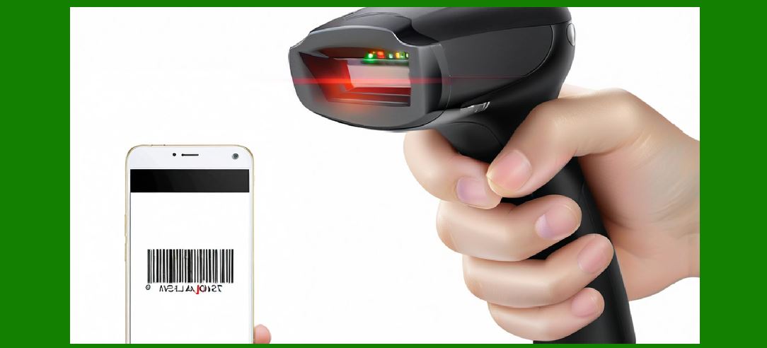
The optical system is the first and most critical stage of a barcode scanner. It is responsible for: |
1. Capturing reflected light from the barcode |
2. Converting physical patterns into optical signals |
3. Delivering accurate image information to sensors |
Without a properly designed optical system, even advanced processors cannot recover reliable data. |
1.2 Core Components of Optical Systems |
A typical barcode scanner optical system includes: |
1. Light source (LED or laser) |
2. Lens system |
3. Optical filters |
4. Sensor (CCD or CMOS) |
5. Reflective surfaces or mirrors (in laser scanners) |
|
2. Light Source Design |
2.1 Types of Light Sources |
2.1.1 LED Illumination |
1. Common in imaging scanners |
2. Provides broad, uniform lighting |
3. Energy-efficient and stable |
2.1.2 Laser Illumination |
1. Used in traditional laser scanners |
2. Produces a focused beam |
3. High intensity over long distance |
2.1.3 Infrared (IR) Illumination |
1. Invisible to human eye |
2. Useful in low-light environments |
3. Reduces user distraction |
2.2 Light Source Characteristics |
Key properties include: |
1. Intensity |
2. Wavelength |
3. Beam angle |
4. Stability over time |

|
3. Optical Path Design |
3.1 Concept of Optical Path |
The optical path defines how light travels from source barcode sensor. |
3.2 Basic Path in Imaging Scanners |
1. Light emitted from LED |
2. Light reflects off barcode surface |
3. Lens collects reflected light |
4. Image focused onto sensor |
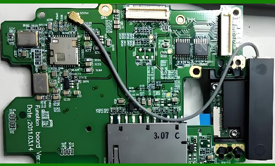
3.3 Laser Scanner Optical Path |
1. Laser beam emitted |
2. Mirror or rotating polygon scans beam |
3. Reflected light returns to photodiode |
4. Signal processed into waveform |
|
4. Lens System Design |
4.1 Function of Lenses |
Lenses are responsible for: |
1. Focusing light |
2. Controlling field of view |
3. Reducing distortion |
4.2 Types of Lenses Used |
4.2.1 Fixed Focus Lenses |
1. No mechanical adjustment |
2. Used in low-cost scanners |
4.2.2 Autofocus Lenses |
1. Adjust focal length dynamically |
2. Used in high-end imaging scanners |
4.2.3 Wide-Angle Lenses |
1. Capture larger scanning area |
2. Useful for omnidirectional scanning |
4.3 Lens Aberrations |
Optical imperfections include: |
1. Chromatic aberration |
2. Spherical distortion |
3. Coma distortion |
These must be corrected digitally or optically. |

|
5. Depth of Field Optimization |
5.1 Definition |
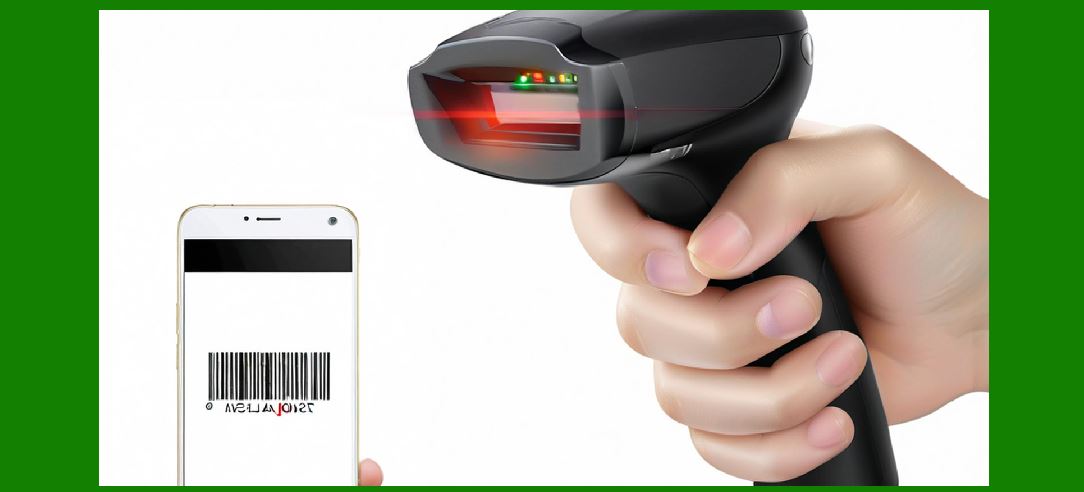
Depth of field is the range in which a barcode remains in focus. |
5.2 Factors Affecting Depth of Field |
1. Lens aperture size |
2. Sensor size |
3. Focal length |
4. Light intensity |
5.3 Trade-Offs |
1. Wide depth lower sharpness |
2. Narrow depth higher precision |
|
6. Field of View (FOV) |
6.1 Definition |
Field of view is the visible area captured by the scanner. |
6.2 Design Considerations |
1. Wide FOV increases scanning flexibility |
2. Narrow FOV increases precision |
6.3 Application Impact |
1. Retail wide FOV for fast scanning |
2. Industrial narrow FOV for precision tasks |

|
7. Optical Filters |
7.1 Purpose of Optical Filters |
Filters improve image quality by: |
1. Removing unwanted light |
2. Enhancing contrast |
3. Reducing glare |
7.2 Types of Filters |
7.2.1 Bandpass Filters |
1. Allow specific wavelengths |
2. Block ambient light interference |
7.2.2 Polarizing Filters |
1. Reduce reflections |
2. Improve readability on glossy surfaces |
|
8. Illumination Engineering |
8.1 Uniform Illumination Design |
1. Even light distribution across barcode |
2. Eliminates shadow zones |
8.2 Diffused Lighting Systems |
1. Softens light source |
2. Reduces glare and hotspots |
8.3 Ring Illumination |
1. Circular LED arrangement |
2. Provides uniform angle lighting |

|
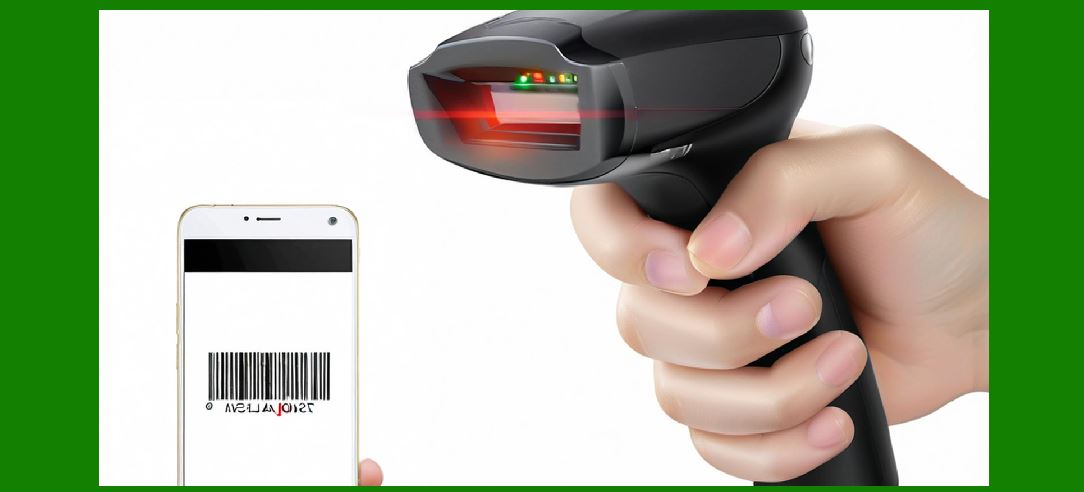
9. Laser Optics in Barcode Scanners |
9.1 Beam Generation |
1. Laser diode emits coherent light |
2. Beam is collimated for directionality |
9.2 Beam Scanning Mechanisms |
1. Rotating mirror systems |
2. Vibrating mirrors (MEMS technology) |
9.3 Photodiode Detection |
1. Converts reflected light into electrical signals |
2. Measures intensity variation |
|
10. Imaging Optics vs Laser Optics |
10.1 Imaging Optics |
1. Captures full image |
2. Uses lenses and sensors |
3. Supports 2D codes |
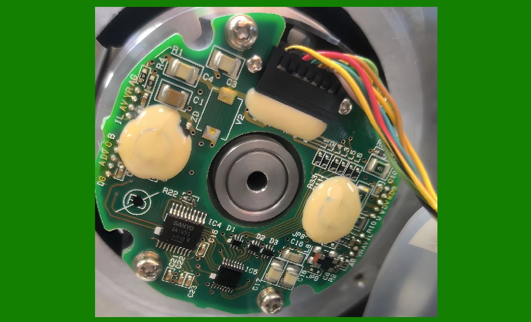
10.2 Laser Optics |
1. Uses single scanning line |
2. Relies on reflectance waveform |
3. Primarily for 1D codes |
10.3 Key Differences |
1. Imaging = full-frame capture |
2. Laser = point-by-point scanning |
|
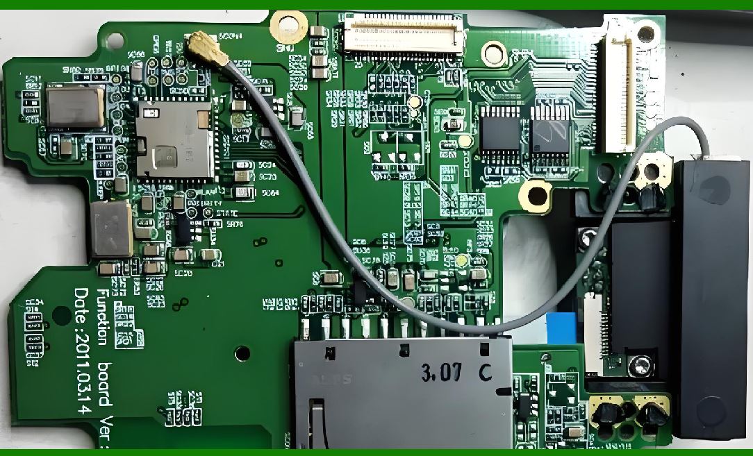
11. Optical Noise and Interference |
11.1 Sources of Noise |
1. Ambient light |
2. Sensor noise |
3. Optical reflection artifacts |
11.2 Noise Reduction Techniques |
1. Optical shielding |
2. Digital filtering |
3. Exposure control |
|
12. Reflection and Surface Interaction |
12.1 Specular Reflection |
1. Occurs on glossy surfaces |
2. Causes bright spots |
12.2 Diffuse Reflection |
1. Occurs on matte surfaces |
2. Provides more uniform data |
12.3 Surface Impact on Scanning |
1. Paper easy scanning |
2. Plastic/glass challenging scanning |

|
13. Optical Calibration Systems |
13.1 Focus Calibration |
1. Ensures sharp image capture |
2. Adjusts lens position |
13.2 Alignment Calibration |
1. Aligns optical axis |
2. Reduces distortion |
13.3 Light Intensity Calibration |
1. Balances brightness levels |
2. Prevents overexposure |
|
14. Advanced Optical Technologies |
14.1 Adaptive Optics |
1. Dynamically adjusts focus |
2. Compensates for distortion |
14.2 Multi-Lens Systems |
1. Multiple optical paths |
2. Improved depth perception |
14.3 Computational Optics |
1. Combines optics + software correction |
2. Reconstructs high-quality images |
|
15. Future Trends in Optical Systems |
15.1 Miniaturized Optics |
1. Ultra-compact lens systems |
2. Embedded optical modules |
15.2 Liquid Lens Technology |
1. Electrically adjustable focus |
2. Fast adaptation to distance changes |
15.3 AI-Enhanced Optical Correction |
1. Real-time distortion correction |
2. Intelligent focus adjustment |
15.4 Quantum Optical Sensing (Emerging) |
1. Ultra-sensitive light detection |
2. Extremely low-energy imaging |
|
16. Summary of Part 16 |
In this section, we explored the optical system design of barcode scanners: |
1. Light source technologies (LED, laser, IR) |
2. Optical path structures |
3. Lens systems and focal control |
4. Depth of field and field of view |
5. Optical filters and illumination engineering |
6. Laser scanning optics |
7. Imaging vs laser optical systems |
8. Optical noise and reflection issues |
9. Calibration techniques |
10. Advanced optical technologies |
11. Future trends in optical engineering |
The optical system is the foundation of barcode scanning accuracy, directly determining how well physical patterns are converted into digital data. |

|
Next Step |
In Part 17, we will explore: |
* Signal processing theory in barcode scanners |
* Analog-to-digital conversion in depth |
* Filtering, noise reduction, and waveform interpretation |
* Mathematical models behind decoding algorithms |
 cs@easiersoft.com