Detailed Explanation of the Principles and Structure of Barcode Scanner |
Part 3: Electronic Architecture, Signal Processing, and Embedded Control Systems |
1. Introduction to Electronic Systems in Barcode Scanners |
1.1 Role of Electronics in Barcode Scanning |
While the optical system captures raw light information, the electronic subsystem transforms that raw signal into meaningful digital data. It acts as the train and nervous system of the scanner. |
Its responsibilities include: |
1. Amplifying weak sensor signals |
2. Filtering noise and interference |
3. Converting analog signals into digital form |
4. Processing data using algorithms |
5. Managing communication with external systems |
Without a well-designed electronic architecture, even the best optical system would fail to produce usable results. |
1.2 Key Electronic Subsystems |
A modern barcode scanner typically includes: |
1. Analog Front End (AFE) |
2. Analog-to-Digital Converter (ADC) |
3. Digital Signal Processor (DSP) or Microcontroller |
4. Memory Units (RAM/Flash) |
5. Interface Controllers (USB, Bluetooth, etc.) |
6. Power Management Circuits |
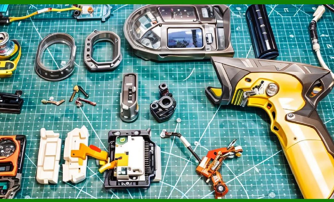
Each subsystem performs a distinct but interconnected role. |
|
2. Analog Front-End (AFE) Design |
2.1 Purpose of the AFE |
The Analog Front-End is responsible for preparing the raw signal from the sensor for digital processing. |
Its main tasks: |
1. Signal amplification |
2. Noise filtering |
3. Signal shaping |
2.2 Signal Amplification |
Sensor outputs are often very weak and require amplification. |
1. Transimpedance Amplifiers (TIA) |
Convert current from photodiodes into voltage |
2. Voltage Amplifiers |
Increase signal strength for further processing |
Amplification must be carefully controlled to avoid distortion. |
2.3 Filtering Techniques |
Filtering removes unwanted components from the signal. |
1. Low-pass filters |
Remove high-frequency noise |
2. High-pass filters |
Eliminate low-frequency drift |
3. Band-pass filters |
Focus on relevant signal frequencies |
2.4 Signal Conditioning |
Signal conditioning ensures that the waveform is suitable for digitization. |
This includes: |
1. Baseline stabilization |
2. Signal normalization |
3. Contrast enhancement |

|
3. Analog-to-Digital Conversion (ADC) |
3.1 Purpose of ADC |
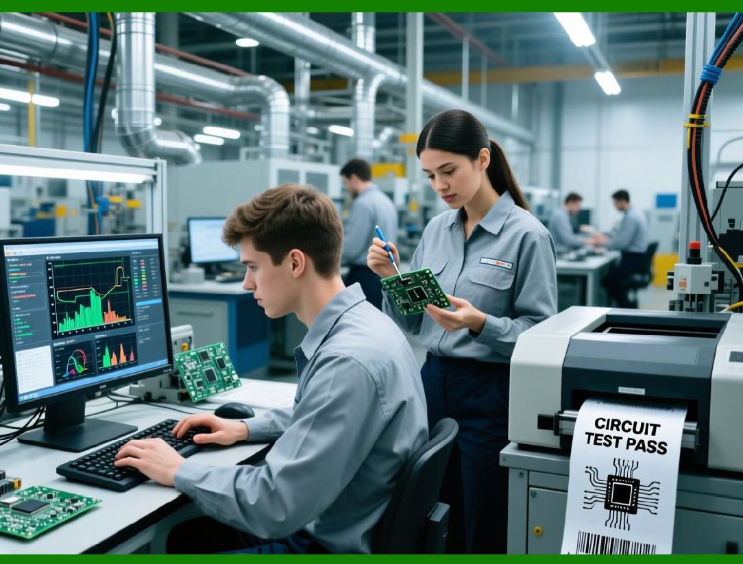
The ADC converts continuous analog signals into discrete digital values. |
This is a critical step because digital systems cannot process analog signals directly. |
3.2 Key Parameters of ADC |
3.2.1 Resolution |
1. Measured in bits (e.g., 8-bit, 12-bit) |
2. Determines precision of conversion |
Higher resolution allows detection of subtle differences in light intensity. |
3.2.2 Sampling Rate |
1. Defines how often the signal is measured |
2. Must be high enough to capture barcode patterns accurately |
3.2.3 Quantization |
1. Converts continuous signal levels into discrete values |
2. Introduces small errors known as quantization noise |
3.3 ADC in Different Scanner Types |
1. Laser scanners require fast sampling |
2. CCD scanners use synchronized sampling |
3. Imaging scanners rely on pixel-level digitization |
|
4. Digital Signal Processing (DSP) |
4.1 Role of DSP in Barcode Scanners |
Once the signal is digitized, it must be processed to extract meaningful patterns. |
DSP performs: |
1. Signal smoothing |
2. Edge detection |
3. Pattern recognition |
4.2 Signal Smoothing |
Reduces noise in the digital signal. |
Techniques include: |
1. Moving average filters |
2. Gaussian filtering |
3. Median filtering |
4.3 Edge Detection |
Edge detection identifies transitions between: |
1. Dark bars |
2. Light spaces |
This is crucial for determining barcode structure. |
4.4 Thresholding |
Thresholding converts grayscale signals into binary values. |
1. Above threshold White (space) |
2. Below threshold Black (bar) |
Adaptive thresholding improves performance under varying lighting conditions. |
4.5 Timing Analysis |
Timing analysis measures the width of bars and spaces. |
1. Determines encoding patterns |
2. Identifies start/stop sequences |
3. Ensures accurate decoding |

|
5. Microcontrollers and Embedded Systems |
5.1 Role of Microcontrollers |
Microcontrollers manage the overall operation of the scanner. |
Responsibilities include: |
1. Coordinating subsystems |
2. Running decoding algorithms |
3. Handling communication protocols |
5.2 Components of a Microcontroller System |
1. CPU core |
2. Memory (RAM and Flash) |
3. Input/output interfaces |
4. Timers and interrupts |
5.3 Firmware in Barcode Scanners |
Firmware is the software embedded within the scanner. |
It controls: |
1. Scanning operations |
2. Signal processing routines |
3. Data formatting |
4. Error handling |
Firmware updates can enhance performance and add new features. |
5.4 Real-Time Processing Requirements |
Barcode scanning requires real-time processing. |
1. Low latency is critical |
2. Fast response improves user experience |
3. Efficient algorithms reduce power consumption |

|
6. Memory Systems |
6.1 Types of Memory |
1. RAM |
Temporary data storage |
2. Flash Memory |
Stores firmware and configuration |
6.2 Buffering Mechanisms |
Buffers store intermediate data during processing. |
1. Input buffers for raw signals |
2. Output buffers for decoded data |
6.3 Data Logging |
Some scanners support: |
1. Batch scanning |
2. Offline data storage |
3. Later synchronization |

|
7. Interface and Communication Modules |
7.1 Wired Interfaces |
7.1.1 USB |
1. Most common interface |
2. Supports plug-and-play operation |
7.1.2 RS-232 |
1. Used in industrial systems |
2. Reliable but slower |
7.1.3 Keyboard Wedge |
1. Emulates keyboard input |
2. Simple integration |
7.2 Wireless Interfaces |
7.2.1 Bluetooth |
1. Short-range communication |
2. Low power consumption |
7.2.2 Wi-Fi |
1. Long-range communication |
2. Supports network integration |
7.2.3 RF Systems |
1. Used in industrial environments |
2. Provide robust connectivity |
7.3 Communication Protocols |
Protocols define how data is transmitted. |
1. Data framing |
2. Error detection |
3. Synchronization |

|
8. Power Management Systems |
8.1 Power Sources |
1. Batteries (for handheld scanners) |
2. External power supplies |
8.2 Power Regulation |
Ensures stable voltage levels. |
1. Voltage regulators |
2. DC-DC converters |
8.3 Energy Efficiency |
Important for portable devices: |
1. Sleep modes |
2. Low-power components |
3. Efficient firmware design |
|
9. Error Detection and Correction Mechanisms |
9.1 Hardware-Level Error Handling |
1. Signal integrity checks |
2. Redundancy circuits |
9.2 Software-Level Error Handling |
1. Checksum validation |
2. Parity checks |
3. Error correction algorithms |
9.3 Fault Tolerance |
Ensures reliable operation even under: |
1. Poor lighting |
2. Damaged barcodes |
3. Electrical interference |
|
10. Embedded System Integration |
10.1 System-on-Chip (SoC) Designs |
Modern scanners often use SoC solutions: |
1. Combine CPU, DSP, and memory |
2. Reduce size and cost |
3. Improve efficiency |
10.2 Modular Design |
Allows: |
1. Easy upgrades |
2. Custom configurations |
3. Flexible deployment |

|
11. Performance Optimization Techniques |
11.1 Hardware Optimization |
1. High-speed processors |
2. Efficient ADCs |
3. Optimized circuit design |
11.2 Software Optimization |
1. Efficient algorithms |
2. Parallel processing |
3. Adaptive techniques |
11.3 Latency Reduction |
1. Fast signal processing |
2. Efficient data transfer |
3. Minimal buffering delays |

|
12. Security Considerations |
12.1 Data Integrity |
Ensures that scanned data is accurate and unaltered. |
12.2 Secure Communication |
1. Encryption |
2. Authentication |
12.3 Firmware Protection |
Prevents unauthorized modifications. |
|
13. Summary of Part 3 |
In this section, we explored the electronic backbone of barcode scanners: |
1. Analog front-end design |
2. Analog-to-digital conversion |
3. Digital signal processing techniques |
4. Microcontrollers and embedded systems |
5. Memory architecture |
6. Communication interfaces |
7. Power management |
8. Error detection and correction |
9. System integration and optimization |
10. Security considerations |
These electronic components transform raw optical signals into accurate, usable digital data. |

|
Next Step |
In Part 4, we will examine: |
* Barcode decoding algorithms in depth |
* 1D barcode decoding logic |
* 2D barcode decoding (QR, Data Matrix) |
* Error correction methods (Reed-Solomon, etc.) |
* Pattern recognition and AI-assisted decoding |
 cs@easiersoft.com