Part 1: Foundations of Image-Based Scanners Principles, Architecture, and Evolution |
1. Introduction to Image-Based Scanners |
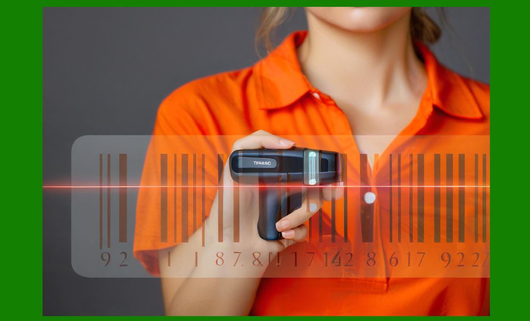
1. Image-based scanners, also known as camera-based barcode scanners or imaging scanners, represent a major evolution from traditional laser and CCD scanning technologies. Unlike earlier systems that rely on reflected light intensity along a single scan line, image-based scanners capture a full two-dimensional image of the target area using digital imaging sensors. |
2. The core concept behind image-based scanning is simple but powerful: instead of interpreting barcode data through analog signal variations, the scanner acquires a digital image, processes it through embedded computing hardware, and extracts encoded information using advanced algorithms. |
3. This approach allows image-based scanners to: |
* Read 1D (linear) barcodes |
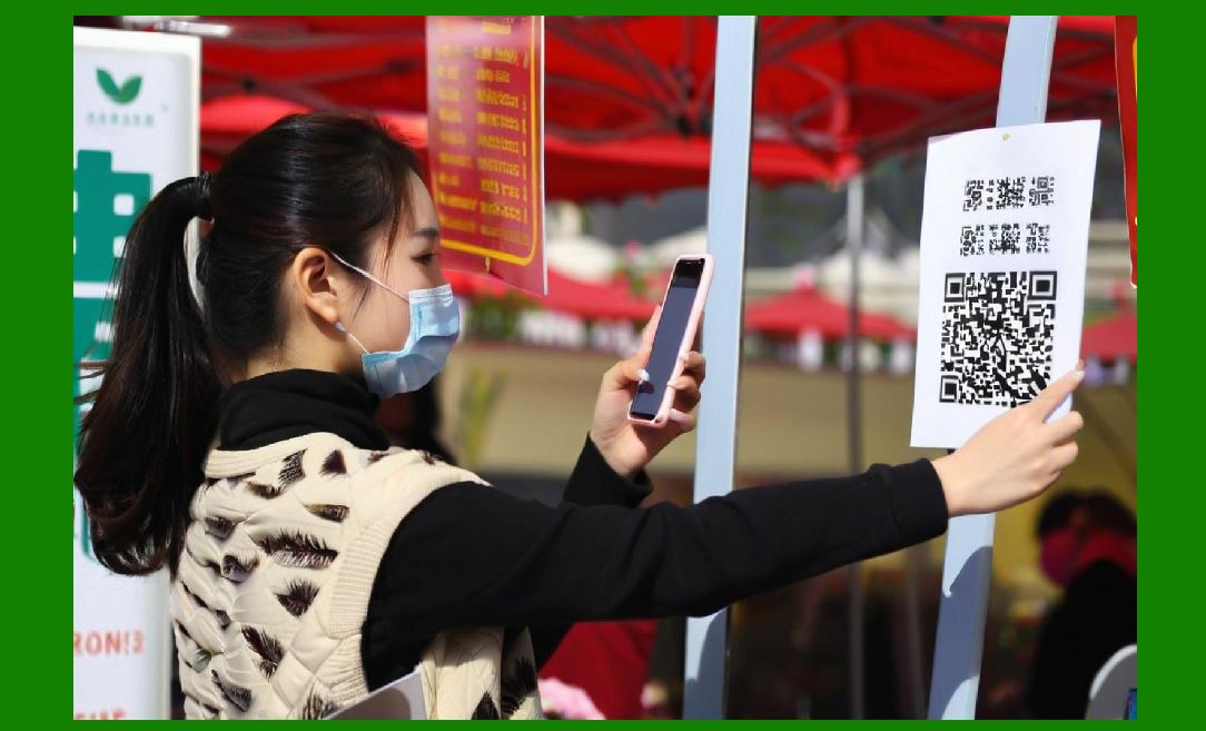
* Decode 2D codes such as QR, Data Matrix, PDF417 |
* Recognize damaged, distorted, or poorly printed codes |
* Capture images for additional purposes (OCR, document capture) |
4. The widespread adoption of image-based scanners is driven by: |
* Growth of mobile and digital ecosystems |
* Increased use of 2D barcodes in logistics and payments |
* Need for higher accuracy and flexibility |
* Integration with computer vision and AI technologies |
|
2. Evolution from Laser and CCD to Imaging Technology |
2.1 Limitations of Laser Scanners |
1. Laser scanners use a moving beam that sweeps across a barcode. |
2. They rely on detecting reflected light intensity differences between bars and spaces. |
3. Limitations include: |
* Cannot read 2D codes |
* Sensitive to orientation |
* Struggles with damaged or low-contrast labels |
* Mechanical components reduce durability |
2.2 CCD (Charge-Coupled Device) Scanners |
1. CCD scanners use a linear array of photodiodes. |
2. They capture a single line of light reflected from the barcode. |
3. Advantages over laser: |
* No moving parts |
* Better durability |
4. Limitations: |
* Still restricted to 1D codes |
* Requires close proximity |
* Limited flexibility |
2.3 Transition to Image-Based Scanners |
1. Image-based scanners replaced linear sensing with 2D image capture. |
2. They leverage: |
* CMOS imaging sensors |
* Embedded processors |
* Digital signal processing |
3. Benefits: |
* Omnidirectional scanning |
* Higher decoding accuracy |
* Support for multiple code types |

|
3. Core Components of Image-Based Scanners |
3.1 Optical System |
1. The optical system focuses light from the barcode onto the sensor. |
2. Key elements: |
* Lens (fixed or adjustable focus) |
* Aperture control |
* Optical filters |
3. Design considerations: |
* Depth of field |
* Field of view |
* Distortion correction |
3.2 Illumination System |
1. Provides consistent lighting for image capture. |
2. Types: |
* LED illumination (most common) |
* Laser illumination (rare in imaging scanners) |
3. Modes: |
* Continuous illumination |
* Pulsed illumination synchronized with exposure |
3.3 Image Sensor (CMOS/CCD) |
1. Converts light into electrical signals. |
2. CMOS sensors dominate due to: |
* Lower power consumption |
* Faster readout |
* Integration with processing circuits |
3.4 Processing Unit |
1. Embedded microcontroller or DSP. |
2. Performs: |
* Image preprocessing |
* Barcode localization |
* Decoding |
3. Often includes: |
* Hardware accelerators |
* AI inference modules (in advanced models) |
3.5 Memory System |
1. Stores: |
* Firmware |
* Image buffers |
* Decoding tables |
2. Includes: |
* Flash memory |
* RAM |
3.6 Communication Interface |
1. Transfers decoded data to host systems. |
2. Interfaces: |
* USB |
* RS-232 |
* Bluetooth |
* Wi-Fi |

|
4. Working Principle of Image-Based Scanners |
4.1 Image Acquisition |
1. The scanner captures an image using a digital camera sensor. |
2. Steps: |
* Illumination activates |
* Sensor exposure occurs |
* Image is digitized |
4.2 Image Preprocessing |
1. Enhances image quality. |
2. Includes: |
* Noise reduction |
* Contrast enhancement |
* Binarization |
4.3 Barcode Detection |
1. Identifies regions containing barcodes. |
2. Techniques: |
* Edge detection |
* Pattern recognition |
* Machine learning (in advanced systems) |
4.4 Decoding |
1. Converts visual patterns into data. |
2. Steps: |
* Symbol segmentation |
* Error correction |
* Data extraction |
4.5 Output Transmission |
1. Data is sent to host systems. |
2. May include: |
* Raw image (optional) |
* Metadata |

|
5. Digital Camera Integration |
5.1 CMOS Sensor Structure |
1. Each pixel contains: |
* Photodiode |
* Amplifier |
* ADC (in some designs) |
2. Advantages: |
* High integration |
* Low cost |
* Fast processing |
5.2 Resolution Considerations |
1. Higher resolution improves: |
* Small code readability |
* Decoding accuracy |
2. Trade-offs: |
* Increased processing requirements |
* Higher power consumption |
5.3 Frame Rate |
1. Determines scanning speed. |
2. Typical range: |
* 3020 frames per second |

|
6. Ability to Read 1D and 2D Codes |
6.1 1D Barcode Reading |
1. Extracts linear patterns from image. |
2. Requires: |
* Line sampling |
* Edge detection |
6.2 2D Barcode Reading |
1. Processes full image. |
2. Supports: |
* QR Code |
* Data Matrix |
* PDF417 |
6.3 Omnidirectional Scanning |
1. No need to align scanner with barcode. |
2. Achieved through: |
* Image rotation |
* Pattern recognition |

|
7. Advanced Decoding Algorithms |
7.1 Image Processing Algorithms |
1. Thresholding |
2. Morphological operations |
3. Perspective correction |
7.2 Error Correction Techniques |
1. Reed-Solomon codes |
2. Checksum validation |
7.3 Machine Learning Enhancements |
1. Neural networks for: |
* Barcode detection |
* Damage recovery |
2. Adaptive decoding strategies |

|
8. Circuit Structure Overview |
8.1 Sensor Interface Circuit |
1. Connects CMOS sensor to processor. |
2. Includes: |
* Clock generation |
* Data bus |
8.2 Power Management Circuit |
1. Regulates voltage. |
2. Ensures stable operation. |
8.3 Processing Circuit |
1. Microcontroller or SoC. |
2. Handles all computation. |
8.4 Communication Circuit |
1. USB controller |
2. Wireless modules |
|
9. Advantages of Image-Based Scanners |
1. High flexibility |
2. Multi-code support |
3. Durability (no moving parts) |
4. Better performance on damaged codes |
5. Future-proof for new barcode standards |

|
10. Challenges and Limitations |
1. Higher cost compared to laser scanners |
2. Increased power consumption |
3. Complex firmware requirements |
4. Sensitivity to lighting conditions |

|
11. Applications |
1. Retail POS systems |
2. Logistics and warehousing |
3. Healthcare |
4. Manufacturing |
5. Mobile payments |
|
12. Summary of Part 1 |
1. Image-based scanners use digital imaging technology to capture and decode barcodes. |
2. They overcome limitations of laser and CCD scanners. |
3. Their architecture includes optics, sensors, processors, and communication modules. |
4. They support both 1D and 2D codes with advanced algorithms. |
5. They represent the current and future direction of barcode scanning technology. |

|
Next Step |
Part 2: Optical Design and Illumination Engineering in Image-Based Scanners (Deep Technical Analysis) |
 cs@easiersoft.com