Part 20: Optical System Engineering and Lens Design in Image-Based Scanners (Deep Technical Analysis) |
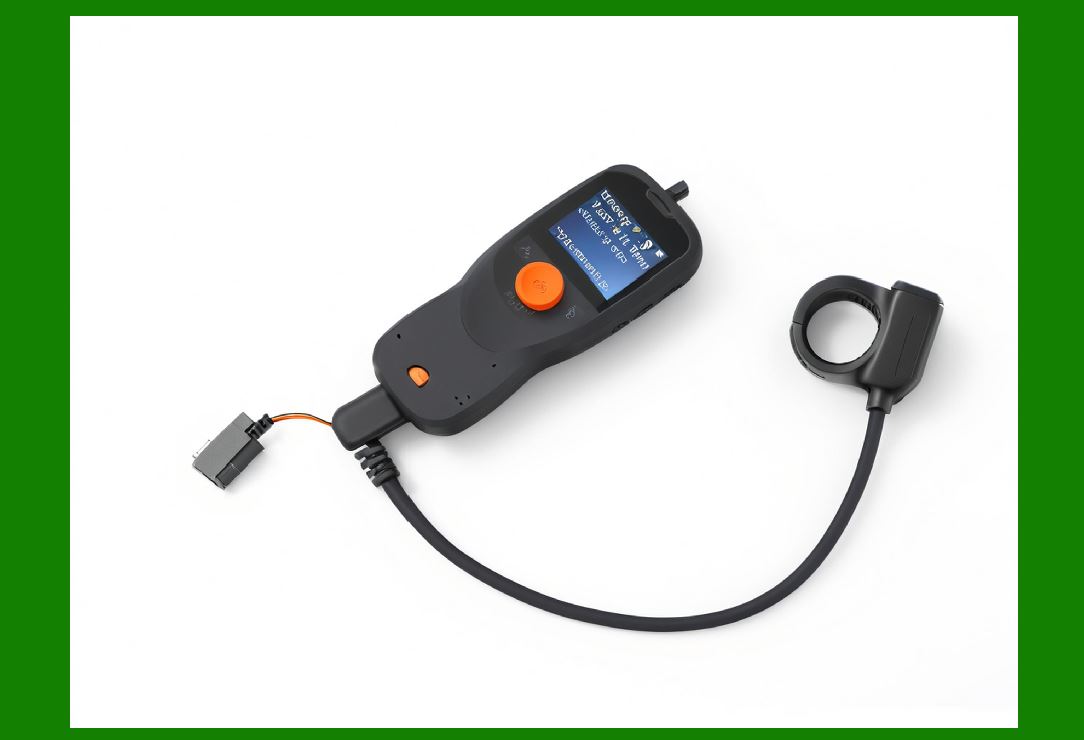
1. Introduction to Optical Engineering in Image-Based Scanners |
1. The optical system is the front-end of the entire imaging pipeline, determining how accurately real-world light patterns are converted into digital signals. |
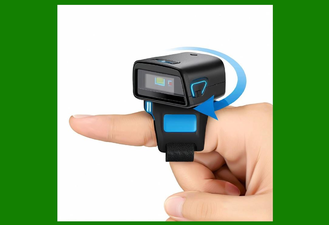
2. In image-based scanners, optical engineering directly affects: |
* Decoding accuracy |
* Depth of field |
* Field of view (FOV) |
* Low-light performance |
* Motion tolerance |
3. Unlike simple cameras, scanner optics are optimized for: |
* High-contrast pattern recognition (not natural image quality) |
* Fast capture cycles |
* Distortion resilience for machine interpretation |
|
2. Core Components of the Optical System |
2.1 Lens Assembly |
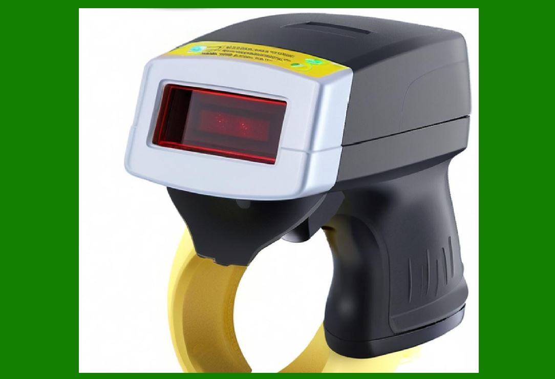
1. Focuses incoming light onto the image sensor. |
2. Key parameters: |
* Focal length |
* Aperture (f-number) |
* Distortion characteristics |
2.2 Image Sensor Plane |
1. Located precisely at the focal plane of the lens system. |
2. Requires: |
* Micrometer-level alignment precision |
2.3 Optical Window |
1. Protective transparent cover. |
2. Must ensure: |
* High transmission |
* Scratch resistance |
* Minimal optical distortion |
2.4 Illumination System (Optical Integration) |
1. LEDs or other light sources integrated into optical path. |

|
3. Lens Design Principles |
3.1 Field of View (FOV) Design |
1. Wide FOV: |
* Enables fast scanning |
* Reduces aiming effort |
2. Narrow FOV: |
* Higher precision |
* Longer reading distance |
3.2 Focal Length Optimization |
1. Short focal length: |
* Wide angle |
* Short working distance |
2. Long focal length: |
* Narrow angle |
* Long-distance scanning |
3.3 Depth of Field (DOF) |
1. Defines range of distances where barcode remains in focus. |
2. Critical in logistics environments with varying object distances. |

|
4. Optical Aberrations and Corrections |
4.1 Types of Aberrations |
1. Spherical aberration |
2. Chromatic aberration |
3. Coma distortion |
4. Astigmatism |
4.2 Correction Techniques |
1. Multi-element lens design |
2. Aspheric lenses |
3. Software correction in ISP |

|
5. Distortion Control in Scanner Optics |
5.1 Barrel Distortion |
1. Causes image edges to curve outward. |
5.2 Pincushion Distortion |
1. Causes inward curvature of image edges. |
5.3 Correction Strategy |
1. Calibration using grid patterns |
2. Real-time geometric correction algorithms |
|
6. Aperture and Light Control |
6.1 Aperture Function |
1. Controls amount of light entering the sensor. |
6.2 Trade-offs |
1. Large aperture: |
* Better low-light performance |
* Shallower depth of field |
2. Small aperture: |
* Greater depth of field |
* Lower brightness |

|
7. Optical Resolution and Sharpness |
7.1 Resolution Factors |
1. Sensor pixel density |
2. Lens resolving power |
3. Optical alignment precision |
7.2 Modulation Transfer Function (MTF) |
1. Measures optical system sharpness. |

|
8. Illumination Optics Integration |
8.1 Coaxial Illumination |
1. Light aligned with optical axis. |
2. Reduces shadows. |
8.2 Off-Axis Illumination |
1. Light angled to enhance contrast. |
8.3 Diffused Illumination |
1. Soft lighting for reflective surfaces. |

|
9. Optical Filtering Systems |
9.1 Bandpass Filters |
1. Allow only specific wavelengths. |
9.2 Polarizing Filters |
1. Reduce glare from reflective surfaces. |
9.3 Infrared Filtering |
1. Eliminates unwanted IR interference. |
|
10. Focus Mechanisms |
10.1 Fixed Focus Systems |
1. No moving parts |
2. Cost-effective |
3. Used in most scanners |
10.2 Auto-Focus Systems (Advanced Models) |
1. Mechanical lens adjustment |
2. Liquid lens technology (emerging) |
10.3 Dynamic Focus Adjustment |
1. Software-assisted focus optimization |
|
11. Optical Alignment and Calibration |
11.1 Assembly Alignment |
1. Lens must align with: |
* Sensor center |
* Optical axis |
11.2 Factory Calibration |
1. Uses test charts and reference targets |
11.3 Field Recalibration |
1. Adjustments based on environment changes |
|
12. Optical Noise Sources |
12.1 Ambient Light Interference |
1. Sunlight |
2. Artificial flickering lights |
12.2 Internal Reflections |
1. Caused by imperfect lens surfaces |
12.3 Sensor Noise Coupling |
1. Optical noise interacts with electronic noise |
|
13. Advanced Optical Technologies |
13.1 Liquid Lenses |
1. Focus adjustment via fluid shape control |
13.2 MEMS Optical Systems |
1. Micro-electromechanical lens systems |
13.3 Diffractive Optical Elements (DOE) |
1. Lightweight optical pattern shaping |

|
14. Miniaturization of Optical Systems |
1. Smartphone-level scanner optics |
2. Folded optical paths |
3. Integrated lens-sensor modules |

|
15. Environmental Protection of Optical Systems |
15.1 Dust Protection |
1. Sealed optical windows |
15.2 Scratch Resistance |
1. Hard coatings (e.g., sapphire-like coatings) |
15.3 Anti-Fogging Measures |
1. Hydrophobic coatings |
|
16. Optical System Performance Trade-offs |
16.1 Resolution vs Speed |
1. Higher resolution requires more processing power |
16.2 FOV vs Distortion |
1. Wider field increases distortion risk |
16.3 Aperture vs Depth of Field |
1. Optical balance is critical for stable decoding |
|
17. Future Optical Engineering Trends |
17.1 Computational Optics |
1. Optical and software systems co-designed |
17.2 Adaptive Optics |
1. Real-time lens adjustment based on environment |
17.3 Flat Optics (Meta-Lenses) |
1. Ultra-thin optical systems using nanostructures |
|
18. Summary of Part 20 |
1. Optical systems define the quality of all downstream processing in image-based scanners. |
2. Lens design balances field of view, depth of field, and distortion. |
3. Illumination and filtering are tightly integrated with optics. |
4. Calibration ensures long-term stability and accuracy. |
5. Future systems will move toward computational and adaptive optical designs. |
|
Next Step |
Part 21: High-Speed Imaging Architecture and Frame Rate Optimization in Image-Based Scanners |
 cs@easiersoft.com