Part 24: Power Management Systems, Energy Efficiency, and Thermal Control in Image-Based Scanners |
1. Introduction to Power and Thermal Engineering |
1. Image-based scanners are embedded systems that must operate under strict energy constraints, especially in handheld, mobile, and battery-powered environments. |
2. At the same time, high-speed image processing generates significant heat inside compact enclosures, requiring careful thermal design. |
3. Therefore, modern scanner design must balance three tightly coupled goals: |
* Low power consumption |
* Stable performance |
* Effective heat dissipation |

|
2. Power System Architecture Overview |
2.1 Main Power Domains |
1. Sensor power domain |
2. Processing power domain (CPU / ISP / DSP) |
3. Communication power domain (USB / Wi-Fi / Bluetooth) |
4. Illumination power domain (LED drivers) |
2.2 Power Distribution Tree |
1. Input power protection stage DC-DC converters LDO regulators subsystems |
2. Each stage is optimized for: |
* Efficiency |
* Noise isolation |
* Load stability |

|
3. Power Supply Input Design |
3.1 Input Sources |
1. USB-powered systems (5V) |
2. Lithium-ion battery packs (3.7V.4V) |
3. Industrial DC supply (12V4V) |
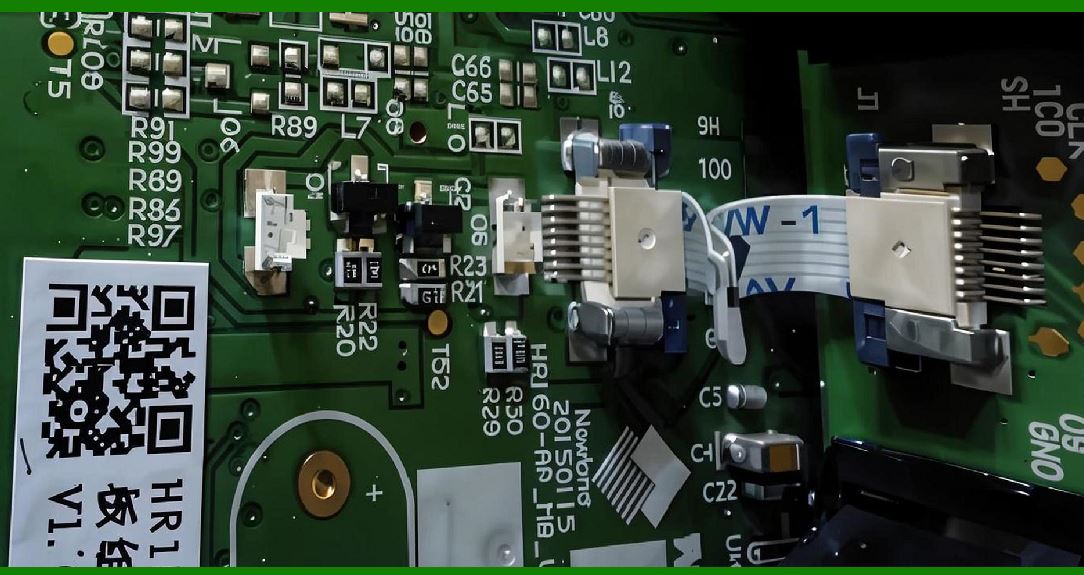
3.2 Protection Circuitry |
1. Over-voltage protection (OVP) |
2. Over-current protection (OCP) |
3. Electrostatic discharge (ESD) protection |
|
4. DC-DC Conversion Efficiency Optimization |
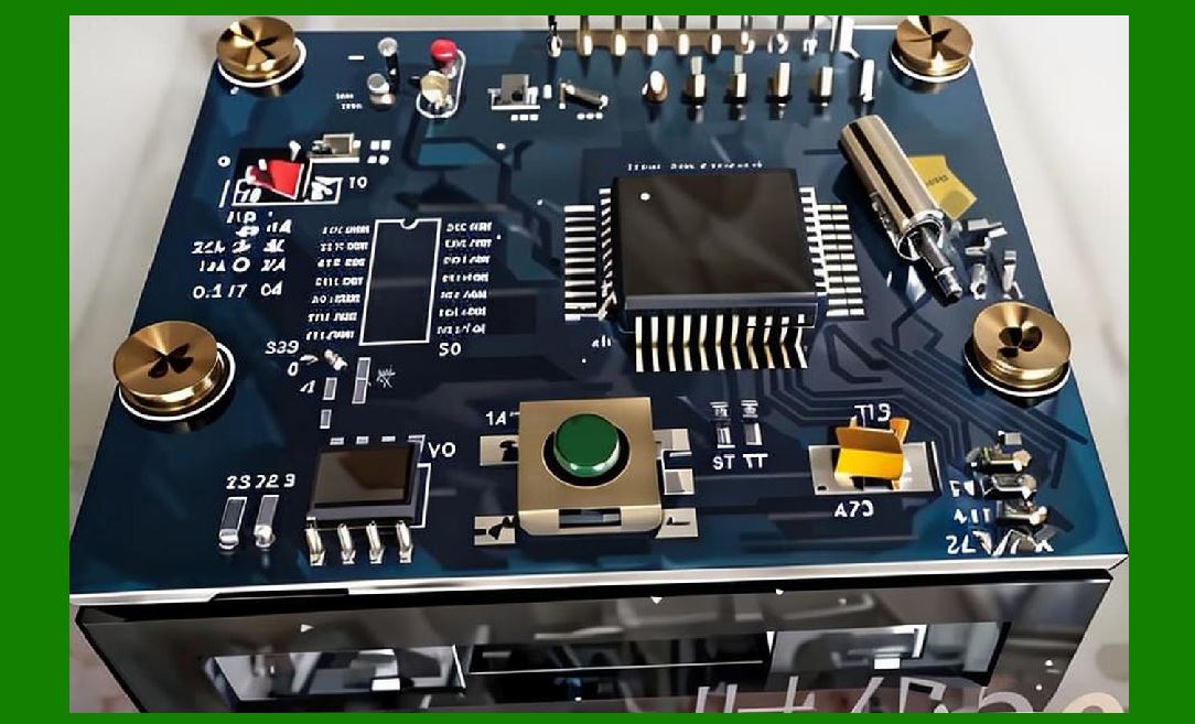
4.1 Switching Regulators |
1. High-efficiency step-down (buck) converters used for: |
* CPU cores |
* Sensors |
4.2 Step-Up Converters |
1. Used for LED illumination systems requiring higher voltage. |
4.3 Efficiency Trade-offs |
1. Higher switching frequency: |
* Smaller components |
* More switching loss |
2. Lower switching frequency: |
* Better efficiency |
* Larger inductors required |
|
5. Low-Dropout Regulators (LDOs) |
5.1 Role of LDOs |
1. Provide clean power to: |
* Image sensors |
* Analog circuits |
5.2 Noise Isolation |
1. LDOs reduce ripple from switching regulators. |

|
6. Dynamic Power Management (DPM) |
6.1 Voltage Scaling |
1. Adjust voltage based on workload: |
* High load higher voltage |
* Idle lower voltage |
6.2 Frequency Scaling |
1. CPU clock speed adjusted dynamically. |
6.3 Power Gating |
1. Completely shuts off unused modules. |
|
7. Illumination Power Control |
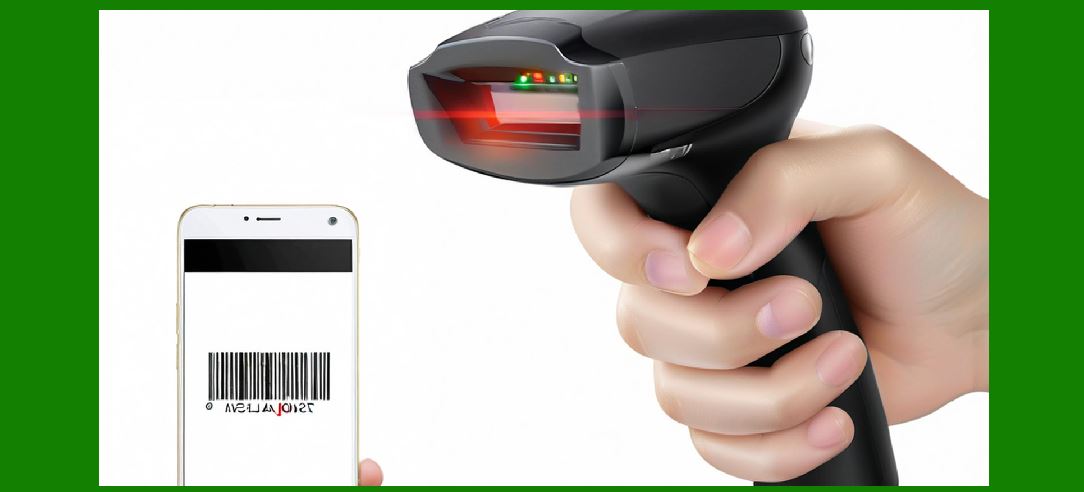
7.1 LED Power Drivers |
1. Constant current control ensures stable brightness. |
7.2 Pulse Width Modulation (PWM) |
1. Adjusts brightness without changing voltage. |
7.3 Strobe Efficiency |
1. LEDs activated only during image capture. |
|
8. Sensor Power Optimization |
8.1 Active vs Idle Modes |
1. Sensors switch between: |
* Active capture mode |
* Low-power standby mode |
8.2 Frame-Based Power Control |
1. Power scaled based on frame rate demand. |

|
9. Processor Power Optimization |
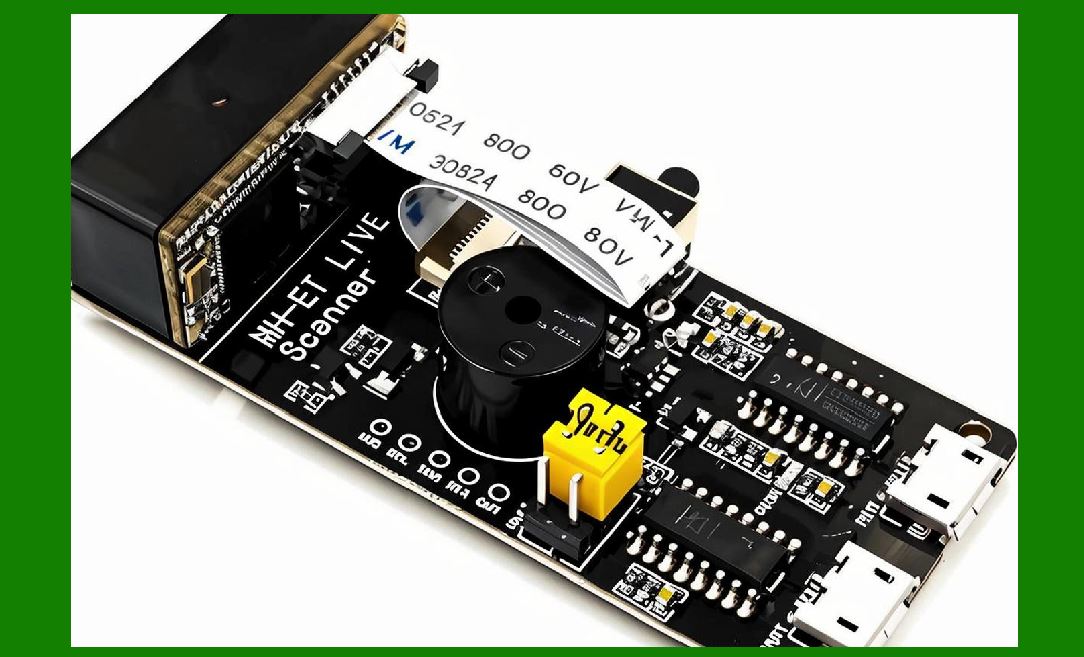
9.1 Clock Gating |
1. Disables unused clock signals. |
9.2 Multi-Core Load Distribution |
1. Balances workload across cores. |
9.3 Hardware Acceleration |
1. Offloads tasks from CPU to specialized blocks. |
|
10. Communication Power Optimization |
10.1 Adaptive Transmission Power |
1. Wireless modules adjust signal strength dynamically. |
10.2 Burst Transmission Mode |
1. Sends data in short high-speed bursts to reduce active time. |

|
11. Thermal Generation Sources |
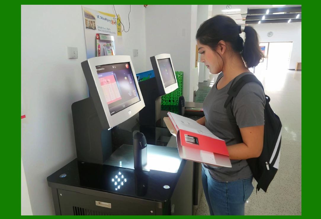
11.1 Main Heat Contributors |
1. Image sensor |
2. CPU / ISP |
3. LED illumination system |
4. Wireless communication module |
|
12. Heat Dissipation Mechanisms |
12.1 Passive Cooling |
1. Aluminum heat spreaders |
2. Thermal pads |
3. PCB copper planes |
12.2 Active Cooling (Rare in handheld devices) |
1. Micro-fans in industrial scanners |
2. Airflow channels |

|
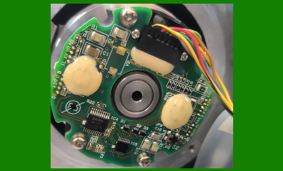
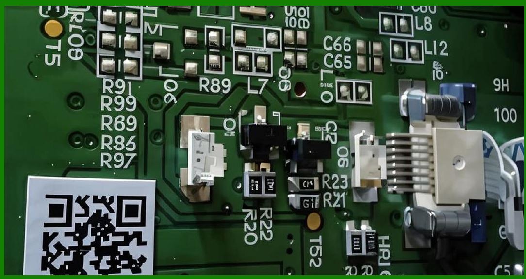
13. Thermal Design of PCB |
13.1 Copper Pour Strategy |
1. Large copper areas distribute heat evenly. |
13.2 Thermal Vias |
1. Conduct heat from hot components to other PCB layers. |
13.3 Component Placement Strategy |
1. Heat-generating components spaced apart. |
|
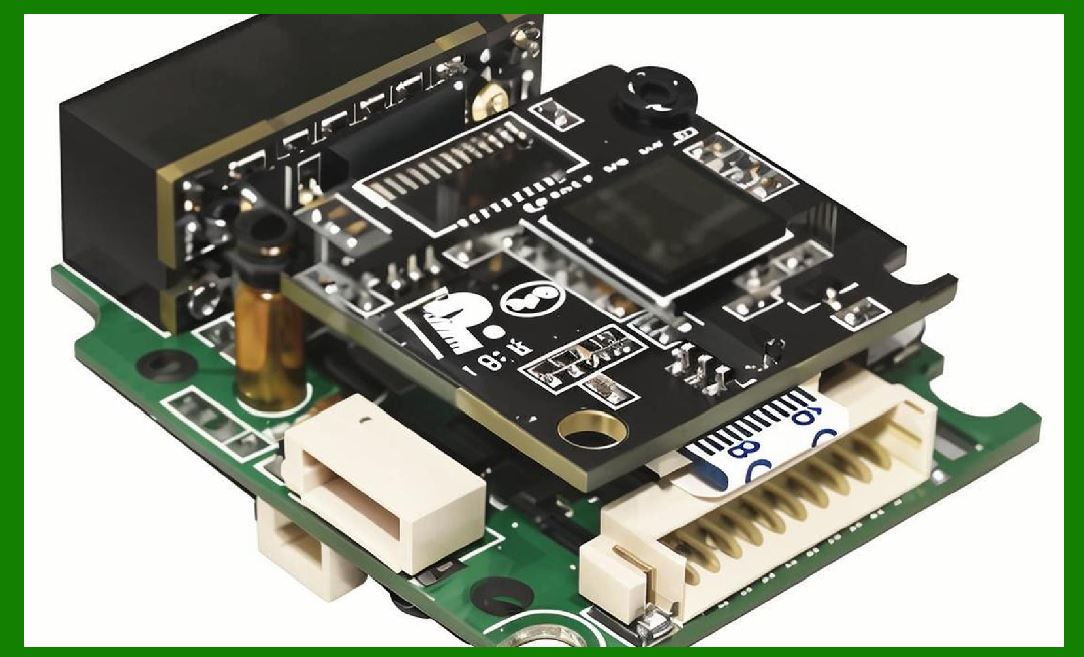
14. Thermal Monitoring Systems |
14.1 Temperature Sensors |
1. Embedded near: |
* CPU |
* Power regulators |
14.2 Thermal Feedback Loop |
1. System reduces performance when temperature rises. |
|
15. Thermal Throttling Mechanisms |
15.1 CPU Frequency Reduction |
1. Automatically reduces processing speed under heat stress. |
15.2 LED Duty Reduction |
1. Reduces illumination intensity. |
15.3 Frame Rate Reduction |
1. Lowers imaging speed to reduce processing load. |
|
16. Battery Management Systems (BMS) |
16.1 Charge Control |
1. Prevents overcharging and deep discharge. |
16.2 Fuel Gauge Monitoring |
1. Estimates remaining battery life. |
16.3 Power Profiling |
1. Predicts energy usage patterns. |
|
17. Energy Efficiency Optimization Strategies |
17.1 Event-Driven Activation |
1. System only activates when scanning is needed. |
17.2 Idle State Minimization |
1. Deep sleep modes reduce energy usage. |
17.3 Component Efficiency Selection |
1. Low-power sensors and SoCs preferred. |
|
18. Industrial Power Requirements |
1. Continuous operation systems require: |
* Stable voltage |
* Redundant power sources |
|
19. Future Trends in Power and Thermal Systems |
19.1 Ultra-Low Power AI Chips |
1. Dedicated low-energy neural processors. |
19.2 Energy Harvesting Scanners |
1. Experimental systems using: |
* Light |
* Vibration |
* RF energy |
19.3 Smart Thermal Materials |
1. Adaptive heat dissipation materials. |
|
20. Summary of Part 24 |
1. Power management is critical for balancing performance and energy efficiency. |
2. Thermal design ensures system stability and longevity. |
3. Dynamic scaling techniques reduce energy waste. |
4. Illumination and processing are major energy consumers. |
5. Future systems will rely on AI-driven power optimization and advanced materials. |

|
Next Step |
Part 25: Manufacturing, Assembly, and Quality Assurance Processes for Image-Based Scanner Systems |
 cs@easiersoft.com