Part 7: Embedded Processing Architecture and Firmware Design in Image-Based Scanners (Deep Technical Analysis) |
1. Introduction to Embedded Processing in Image-Based Scanners |
1. The embedded processing subsystem is the central control and computation unit of an image-based scanner. It orchestrates all operations, including image acquisition, preprocessing, localization, decoding, and communication. |
2. Unlike general-purpose computing systems, barcode scanners require: |
* Real-time responsiveness |
* Deterministic execution |
* Low power consumption |
* High reliability |
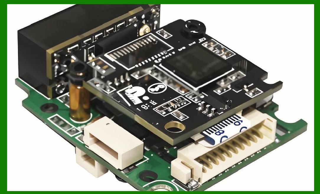
3. The embedded architecture integrates: |
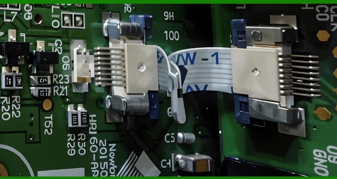
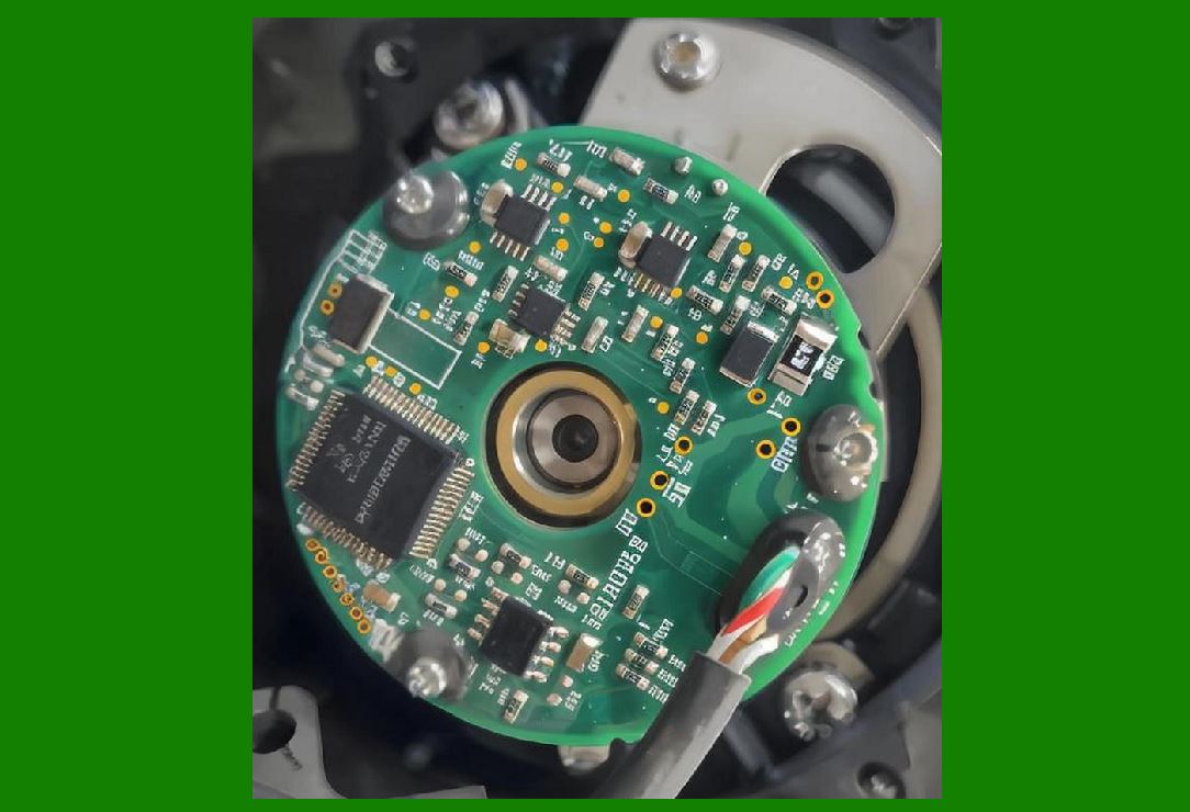
* Processing cores (MCU, DSP, or SoC) |
* Memory subsystems |
* Hardware accelerators |
* Peripheral interfaces |

|
2. System Architecture Overview |
2.1 Functional Blocks |
1. Image Sensor Interface |
2. Image Signal Processor (ISP) |
3. CPU/DSP Core |
4. Hardware Accelerators |
5. Memory System |
6. Communication Interfaces |
7. Power Management Unit |
2.2 Data Flow |
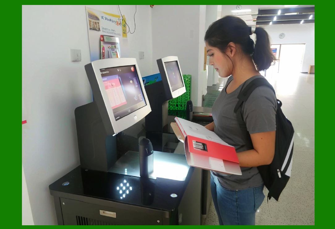
1. Image captured by sensor |
2. Transferred to memory buffer |
3. Processed by ISP |
4. Analyzed by decoding engine |
5. Output transmitted to host |
|
3. Processor Types Used in Scanners |
3.1 Microcontroller Units (MCUs) |
1. Characteristics: |
* Low power consumption |
* Integrated peripherals |
* Moderate processing capability |
2. Suitable for: |
* Entry-level scanners |
* Simple decoding tasks |
3.2 Digital Signal Processors (DSPs) |
1. Optimized for: |
* Mathematical operations |
* Signal processing |
2. Advantages: |
* Fast image processing |
* Efficient filtering |
3.3 System-on-Chip (SoC) |
1. Combines: |
* CPU |
* GPU (optional) |
* ISP |
* Memory controllers |
2. Benefits: |
* High integration |
* Reduced latency |
* Compact design |
3.4 AI-Enabled Processors |
1. Include: |
* Neural Processing Units (NPUs) |
2. Used for: |
* AI-based detection |
* Advanced decoding |
|
4. Memory Architecture |
4.1 Types of Memory |
1. RAM (Volatile) |
* Stores image buffers |
* Temporary data |
2. Flash Memory (Non-volatile) |
* Stores firmware |
* Configuration data |
4.2 Memory Hierarchy |
1. Registers (fastest) |
2. Cache memory |
3. Main RAM |
4. External memory |
4.3 Buffer Management |
1. Double buffering: |
* One buffer for capture |
* One for processing |
2. Circular buffers for streaming data |

|
5. Firmware Architecture |
5.1 Firmware Layers |
1. Hardware Abstraction Layer (HAL) |
2. Device Drivers |
3. Middleware |
4. Application Layer |
5.2 Hardware Abstraction Layer |
1. Provides: |
* Standard interface to hardware |
2. Benefits: |
* Portability |
* Simplified development |
5.3 Device Drivers |
1. Control hardware components: |
* Image sensor |
* Communication interfaces |
* LEDs |
5.4 Middleware |
1. Provides reusable services: |
* Image processing libraries |
* Decoding libraries |
5.5 Application Layer |
1. Implements: |
* Scanning logic |
* User interaction |
* Data output |

|
6. Real-Time Operating Systems (RTOS) |
6.1 Role of RTOS |
1. Manages: |
* Task scheduling |
* Resource allocation |
6.2 Key Features |
1. Deterministic timing |
2. Priority-based scheduling |
3. Interrupt handling |
6.3 Task Management |
1. Tasks include: |
* Image acquisition |
* Processing |
* Communication |

|
7. Interrupt and Event Handling |
7.1 Interrupt Sources |
1. Image sensor ready signal |
2. Communication events |
3. User input (trigger press) |
7.2 Interrupt Handling Strategy |
1. Minimize processing in ISR |
2. Delegate tasks to main loop |
|
8. Parallel Processing and Optimization |
8.1 Multi-Core Processing |
1. Divide tasks across cores: |
* Core 1: Image acquisition |
* Core 2: Processing |
8.2 SIMD and Vector Processing |
1. Accelerate: |
* Filtering |
* Edge detection |
8.3 Hardware Acceleration |
1. Dedicated modules for: |
* ISP |
* Decoding |

|
9. Power Management in Embedded Systems |
9.1 Power States |
1. Active mode |
2. Idle mode |
3. Sleep mode |
9.2 Dynamic Power Control |
1. Adjust: |
* CPU frequency |
* Voltage levels |
9.3 Energy Optimization Techniques |
1. Duty cycling |
2. Selective module activation |
|
10. Firmware Update Mechanisms |
10.1 Over-the-Air (OTA) Updates |
1. Wireless firmware upgrades |
10.2 USB-Based Updates |
1. Firmware flashing via host device |
10.3 Bootloader Design |
1. Ensures safe updates |
2. Provides recovery mechanism |

|
11. Security in Firmware Design |
11.1 Secure Boot |
1. Verifies firmware integrity |
11.2 Encryption |
1. Protects data transmission |
11.3 Access Control |
1. Restricts unauthorized use |
|
12. Debugging and Testing |
12.1 Debug Interfaces |
1. JTAG |
2. UART |
12.2 Testing Methods |
1. Unit testing |
2. Integration testing |
3. Field testing |

|
13. Scalability and Modularity |
1. Modular firmware design allows: |
* Easy upgrades |
* Feature expansion |

|
14. Integration with Hardware Components |
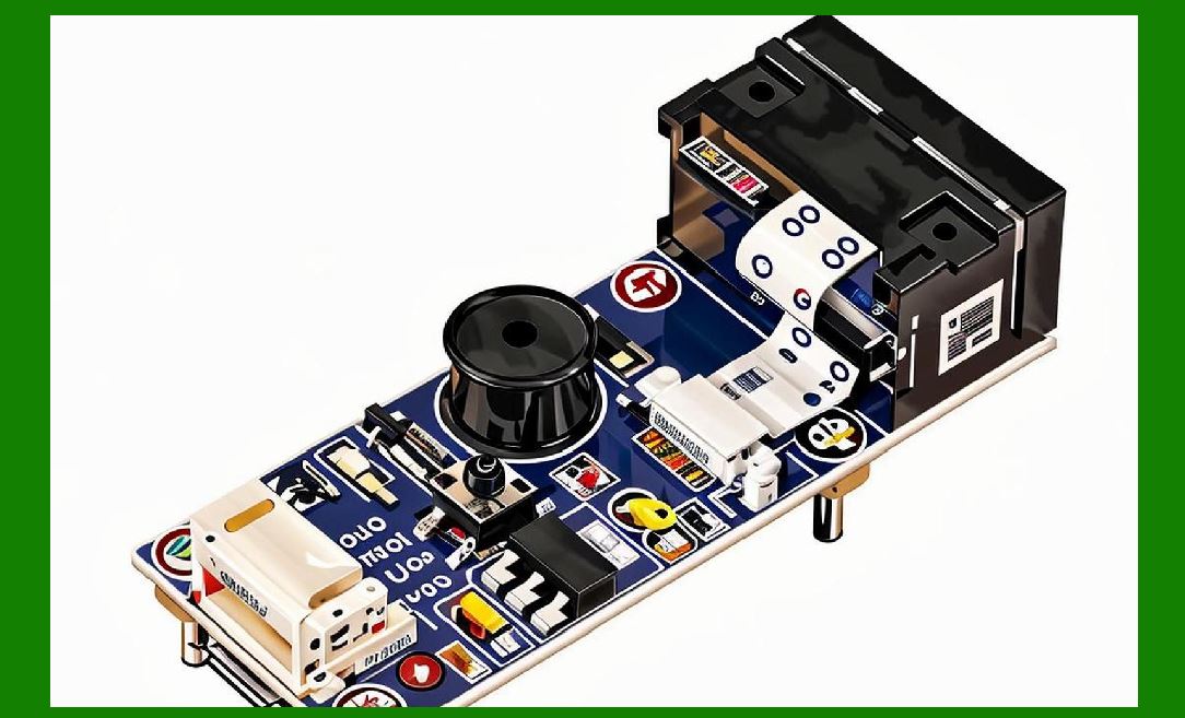
1. Synchronization with: |
* Sensor |
* Illumination |
* Communication modules |
|
15. Performance Metrics |
1. Latency |
2. Throughput |
3. Power consumption |
4. Reliability |

|
16. Future Trends in Embedded Processing |
16.1 AI Integration |
1. Real-time inference |
16.2 Edge Computing |
1. On-device data processing |
16.3 Increased Integration |
1. More functions in single chip |

|
17. Summary of Part 7 |
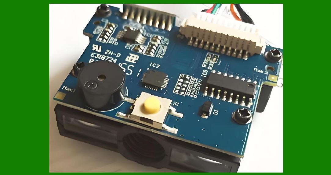
1. Embedded processing is the core of image-based scanners. |
2. It integrates hardware and firmware for real-time operation. |
3. Efficient architecture ensures high performance and low power usage. |
4. RTOS and modular firmware improve reliability and scalability. |
5. Future systems will increasingly incorporate AI and edge computing. |
|
Next Step |
Part 8: Communication Interfaces and Data Transmission in Image-Based Scanners (Deep Technical Analysis) |
 cs@easiersoft.com