Part 8: Communication Interfaces and Data Transmission in Image-Based Scanners (Deep Technical Analysis) |
1. Introduction to Communication Systems in Image-Based Scanners |
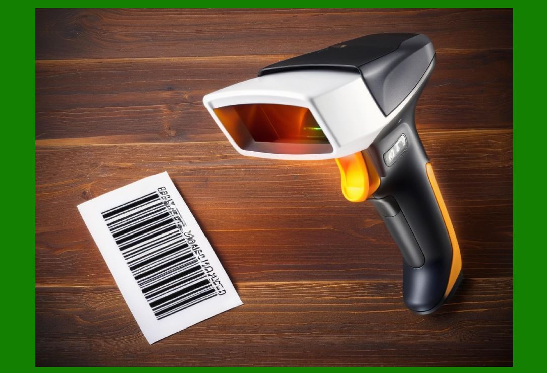
1. The communication subsystem is responsible for transferring decoded barcode data (and sometimes images or metadata) from the scanner to external host systems such as computers, POS terminals, mobile devices, or industrial controllers. |
2. In modern image-based scanners, communication design must satisfy: |
* Low latency (real-time response) |
* High reliability (error-free transmission) |
* Compatibility with multiple host systems |
* Flexibility for wired and wireless environments |
* Security for sensitive data |
3. Communication is not limited to data output; it also includes: |
* Device configuration |
* Firmware updates |
* Status reporting |
* Control commands |
|
2. Communication Architecture Overview |
2.1 Functional Layers |
1. Physical Layer (hardware interface) |
2. Data Link Layer (framing and error detection) |
3. Transport Layer (data flow management) |
4. Application Layer (data interpretation and commands) |
2.2 Data Flow Process |
1. Barcode decoded by processing unit |
2. Data formatted into protocol-specific structure |
3. Packetized for transmission |
4. Sent through interface hardware |
5. Received and interpreted by host system |

|
3. Wired Communication Interfaces |
3.1 USB Interface |
3.1.1 Overview |
1. Universal Serial Bus (USB) is the most widely used interface in barcode scanners. |
2. Advantages: |
* Plug-and-play capability |
* High data transfer speed |
* Power supply through cable |
3.1.2 USB Modes |
1. HID (Human Interface Device) Mode |
* Emulates keyboard input |
* No driver installation required |
2. CDC (Communication Device Class) Mode |
* Virtual COM port |
* Allows custom communication |
3. Bulk Transfer Mode |
* High-speed data transfer |
* Used for image transmission |
3.1.3 USB Data Handling |
1. Data packets structured with: |
* Headers |
* Payload |
* Error checking |
3.2 RS-232 Serial Communication |
3.2.1 Overview |
1. Legacy but still widely used in industrial systems. |
2. Characteristics: |
* Simple implementation |
* Long cable support |
3.2.2 Data Format |
1. Frame includes: |
* Start bit |
* Data bits |
* Parity bit (optional) |
* Stop bits |
3.2.3 Limitations |
1. Lower speed compared to USB |
2. Requires level shifting circuitry |
3.3 Ethernet Communication |
3.3.1 Overview |
1. Used in industrial and networked environments. |
2. Advantages: |
* Long-distance communication |
* Network integration |
3.3.2 Protocols |
1. TCP/IP for reliable transmission |
2. UDP for low-latency communication |
3.4 Other Wired Interfaces |
1. PS/2 (legacy keyboard interface) |
2. CAN Bus (industrial systems) |
3. SPI/I2C (internal communication) |
|
4. Wireless Communication Interfaces |
4.1 Bluetooth Communication |
4.1.1 Overview |
1. Widely used for handheld scanners. |
2. Advantages: |
* Cable-free operation |
* Low power consumption |
4.1.2 Bluetooth Profiles |
1. HID profile (keyboard emulation) |
2. SPP (Serial Port Profile) |
4.1.3 Challenges |
1. Interference |
2. Pairing complexity |
4.2 Wi-Fi Communication |
4.2.1 Overview |
1. Used for high-speed wireless data transmission. |
2. Advantages: |
* Network connectivity |
* Remote management |
4.2.2 Applications |
1. Warehouse systems |
2. Cloud-based data collection |
4.3 NFC and RFID Integration |
1. Short-range communication |
2. Used for: |
* Device pairing |
* Authentication |
|
5. Data Formatting and Protocols |
5.1 Data Formatting |
1. Decoded data must be formatted for transmission. |
2. Common formats: |
* ASCII text |
* Binary data |
* Structured formats (JSON, XML) |
5.2 Communication Protocols |
1. Proprietary protocols |
2. Standard protocols (e.g., TCP/IP, HTTP) |
5.3 Packet Structure |
1. Header (control information) |
2. Payload (data) |
3. Checksum or CRC |

|
6. Error Detection and Correction |
6.1 Error Detection Methods |
1. Parity bits |
2. Checksums |
3. Cyclic Redundancy Check (CRC) |
6.2 Error Handling |
1. Retransmission |
2. Acknowledgment (ACK/NACK) |

|
7. Data Throughput and Latency |
7.1 Throughput Requirements |
1. Depends on: |
* Scan rate |
* Data size |
7.2 Latency Considerations |
1. Real-time applications require: |
* Minimal delay |
7.3 Optimization Techniques |
1. Buffering |
2. Efficient packetization |
|
8. Power Considerations in Communication |
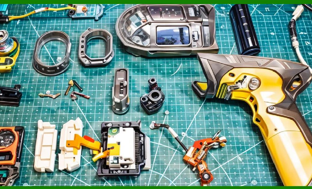
1. Wireless communication consumes more power. |
2. Optimization: |
* Sleep modes |
* Adaptive transmission |
|
9. Multi-Device Connectivity |
1. Support for multiple host connections. |
2. Methods: |
* Multiplexing |
* Network addressing |

|
10. Security in Data Transmission |
10.1 Encryption |
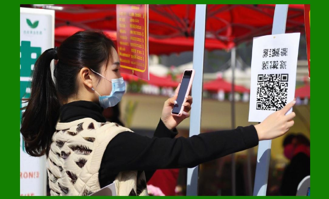
1. Protects sensitive data. |
2. Methods: |
* AES encryption |
* TLS for network communication |
10.2 Authentication |
1. Ensures authorized access. |
10.3 Secure Pairing |
1. Important for Bluetooth devices. |
|
11. Firmware and Protocol Integration |
1. Communication stack implemented in firmware. |
2. Includes: |
* Drivers |
* Protocol handlers |

|
12. Image and Metadata Transmission |
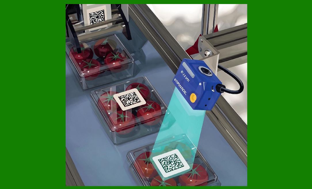
1. Some scanners transmit: |
* Captured images |
* Diagnostic data |
12.1 Compression Techniques |
1. Reduce bandwidth usage: |
* JPEG |
* PNG |
|
13. Real-Time Communication Challenges |
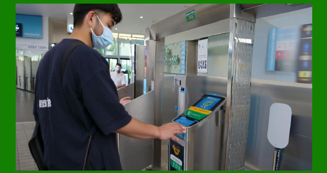
1. Network congestion |
2. Interference (wireless) |
3. Synchronization issues |
|
14. Industrial Communication Standards |
1. Modbus |
2. OPC |
3. Industrial Ethernet |
15. Integration with Host Systems |
1. POS systems |
2. Warehouse management systems |
3. ERP systems |
|
16. Future Trends in Communication |
16.1 IoT Integration |
1. Cloud connectivity |
2. Remote monitoring |
16.2 5G and Advanced Wireless |
1. High-speed, low-latency communication |
16.3 Edge-to-Cloud Systems |
1. Distributed data processing |
|
17. Summary of Part 8 |
1. Communication interfaces enable data exchange between scanners and host systems. |
2. Both wired and wireless technologies are widely used. |
3. Protocols and data formatting ensure compatibility and reliability. |
4. Security and power efficiency are critical considerations. |
5. Future systems will integrate with IoT and cloud platforms. |
|
Next Step |
Part 9: Power Supply Design and Energy Management in Image-Based Scanners (Deep Technical Analysis) |
 cs@easiersoft.com