Part 9: Power Supply Design and Energy Management in Image-Based Scanners (Deep Technical Analysis) |
1. Introduction to Power Systems in Image-Based Scanners |
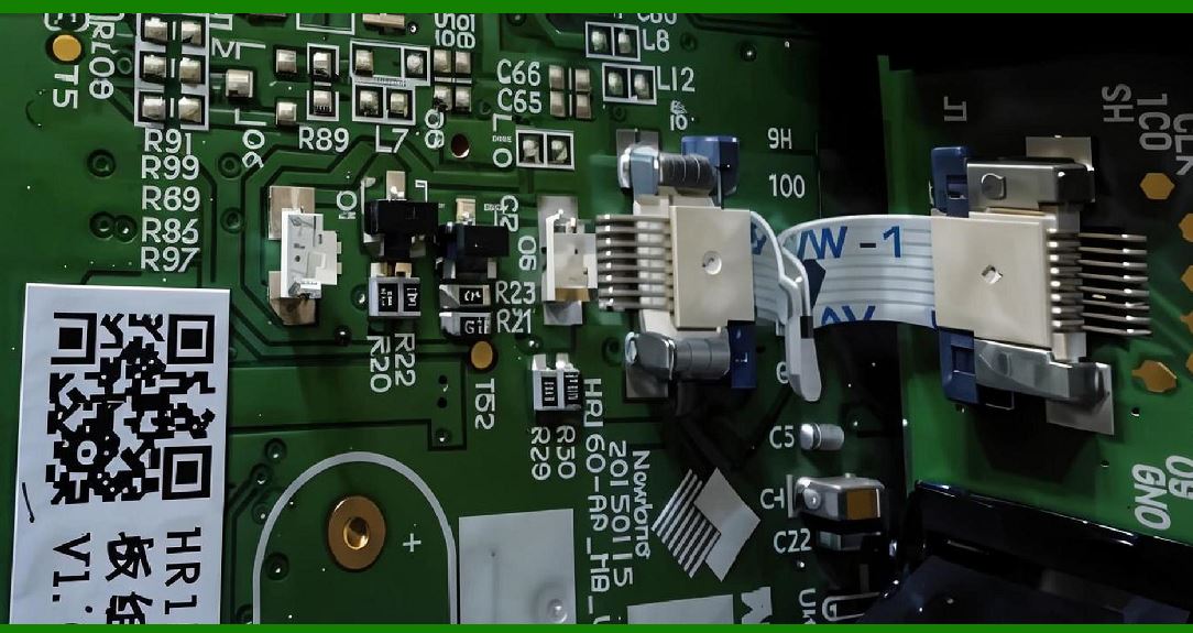
1. The power subsystem is a foundational element in image-based scanners, ensuring that all electronic components ranging from CMOS sensors to processors and communication modules operate reliably and efficiently. |
2. Power design must satisfy multiple constraints: |
* Stable voltage supply |
* Low noise interference |
* High efficiency |
* Thermal control |
* Support for portable and fixed installations |
3. Image-based scanners present unique challenges due to: |
* High peak power demand (during illumination and processing) |
* Low idle power requirements |
* Mixed-signal circuitry sensitivity |
|
2. Power Architecture Overview |
2.1 Power Flow Structure |
1. External power source (USB, battery, adapter) |
2. Input protection and filtering |
3. Voltage regulation stages |
4. Power distribution network |
5. Load components (sensor, MCU, LEDs, communication modules) |
2.2 Multiple Voltage Domains |
1. Different components require different voltage levels: |
* CMOS sensor: typically 1.2V.3V |
* MCU/SoC: 1.0V.8V core, 3.3V I/O |
* LEDs: higher current, varying voltage |
* Communication modules: 1.8VV |
2. Requires: |
* Multiple regulators |
* Careful sequencing |

|
3. Power Sources |
3.1 USB Power Supply |
1. Common in wired scanners. |
2. Standard voltages: |
* 5V (USB 2.0/3.0) |
3. Advantages: |
* No separate power adapter |
* Stable supply |
4. Limitations: |
* Current limits (e.g., 500 mA for USB 2.0) |
3.2 Battery Power |
1. Used in handheld wireless scanners. |
2. Battery types: |
* Lithium-ion (Li-ion) |
* Lithium-polymer (Li-Po) |
3. Design considerations: |
* Capacity vs weight |
* Charging cycles |
* Safety |
3.3 External Power Adapters |
1. Used in industrial or fixed scanners. |
2. Provide: |
* Higher power capacity |
* Stable voltage |

|
4. Voltage Regulation |
4.1 Linear Regulators (LDOs) |
1. Provide clean, low-noise output. |
2. Advantages: |
* Simplicity |
* Low ripple |
3. Disadvantages: |
* Low efficiency (especially with large voltage drops) |
4.2 Switching Regulators (DC-DC Converters) |
1. Types: |
* Buck (step-down) |
* Boost (step-up) |
* Buck-boost |
2. Advantages: |
* High efficiency |
* Suitable for battery-powered systems |
3. Disadvantages: |
* Switching noise |
* More complex design |
4.3 Hybrid Regulation Strategy |
1. Combine: |
* DC-DC for efficiency |
* LDO for noise-sensitive circuits |

|
5. Power Distribution Network (PDN) |
5.1 PCB Power Routing |
1. Use: |
* Wide traces for high current paths |
* Dedicated power planes |
2. Minimize voltage drops. |
5.2 Decoupling and Bypass Capacitors |
1. Stabilize voltage at load points. |
2. Types: |
* Bulk capacitors (low frequency) |
* Ceramic capacitors (high frequency) |
5.3 Grounding Strategy |
1. Separate: |
* Analog ground |
* Digital ground |
2. Prevent noise coupling. |

|
6. Power Sequencing |
1. Certain components must be powered in a specific order. |
2. Example: |
* Core voltage before I/O voltage |
3. Implemented using: |
* Power management ICs (PMICs) |
* Firmware control |

|
7. Power Consumption Analysis |
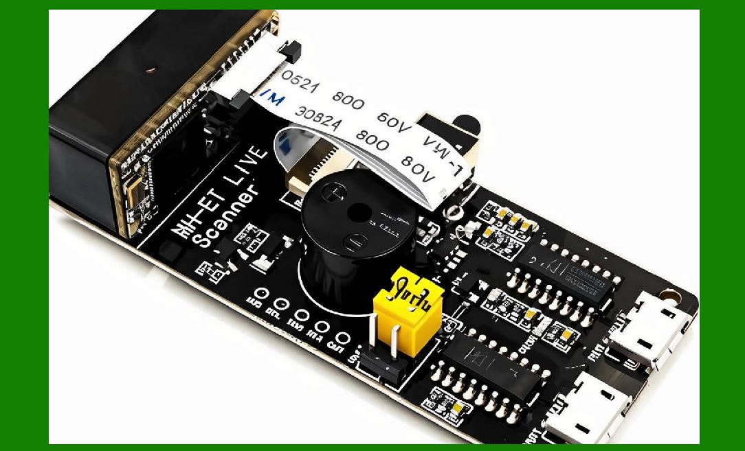
7.1 Major Power Consumers |
1. Illumination system (LEDs) |
2. Image sensor |
3. Processing unit |
4. Wireless communication modules |
7.2 Power Profiles |
1. Idle mode: minimal consumption |
2. Active scanning: peak consumption |
3. Transmission: moderate to high consumption |
|
8. Energy Optimization Techniques |
8.1 Duty Cycling |
1. Turn components on only when needed. |
2. Example: |
* LED flashes only during capture |
8.2 Dynamic Voltage and Frequency Scaling (DVFS) |
1. Adjust processor performance based on workload. |
8.3 Power Gating |
1. Completely shut down unused modules. |

|
9. Thermal Management |
9.1 Heat Sources |
1. LEDs |
2. Processors |
3. Power regulators |
9.2 Cooling Methods |
1. Passive cooling: |
* Heat sinks |
* Thermal pads |
2. Active cooling (rare in scanners) |
9.3 Thermal Protection |
1. Temperature sensors |
2. Automatic shutdown mechanisms |

|
10. Battery Management Systems (BMS) |
10.1 Charging Circuits |
1. Control charging current and voltage. |
2. Prevent: |
* Overcharging |
* Overheating |
10.2 Protection Features |
1. Over-voltage protection |
2. Over-current protection |
3. Short-circuit protection |
10.3 Fuel Gauging |
1. Estimates remaining battery capacity. |
|
11. Power Noise and Signal Integrity |
11.1 Noise Sources |
1. Switching regulators |
2. Digital circuits |
11.2 Noise Mitigation |
1. Filtering |
2. Shielding |
3. Proper PCB layout |

|
12. EMI/EMC Considerations |
1. Power circuits can generate electromagnetic interference. |
2. Compliance with standards: |
* FCC |
* CE |
3. Techniques: |
* Shielding |
* Filtering |
* Grounding |

|
13. Power Monitoring and Diagnostics |
1. Measure: |
* Voltage |
* Current |
* Temperature |
2. Used for: |
* Fault detection |
* Performance optimization |

|
14. Reliability and Safety |
1. Ensure stable operation under: |
* Voltage fluctuations |
* Temperature extremes |
2. Include: |
* Protection circuits |
* Redundancy (in critical systems) |

|
15. Design Trade-offs |
1. Efficiency vs noise |
2. Cost vs performance |
3. Size vs battery capacity |
|
16. Future Trends in Power Design |
16.1 Ultra-Low Power Designs |
1. For IoT-enabled scanners |
16.2 Energy Harvesting |
1. Supplement battery power |
16.3 Advanced Battery Technologies |
1. Higher energy density |
2. Faster charging |

|
17. Summary of Part 9 |
1. Power design is critical for stable and efficient scanner operation. |
2. Multiple voltage domains require careful regulation and sequencing. |
3. Energy optimization techniques extend battery life and reduce heat. |
4. Noise and EMI control are essential for reliable performance. |
5. Future designs will focus on efficiency and integration. |
|
Next Step |
Part 10: Mechanical Design, Ergonomics, and Industrial Engineering of Image-Based Scanners (Deep Technical Analysis) |
 cs@easiersoft.com