1. Introduction to the Barcode Scanner and Its Core Circuitry |
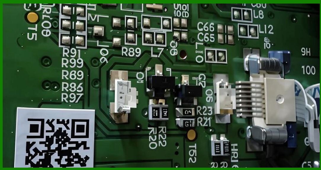
The barcode scanner, in its most essential form, is an electromechanical and optoelectronic system designed to read graphical codes printed on labels, packaging, or documents, and convert them into digital data usable by computers. At the heart of this system lies the main circuit board, which acts as the central nervous system, managing all incoming signals from sensors, controlling light sources, executing data decoding, and facilitating communication with external devices such as POS terminals or warehouse management systems. The principle and design of this circuit board determine the efficiency, accuracy, and reliability of the scanner. Understanding its design requires an exploration of both the theoretical foundation and the practical engineering compromises involved. |
2. Historical Evolution of Barcode Scanner Circuit Boards |
The design of main circuit boards has undergone significant transformation since the earliest barcode readers in the 1970s. Initially, the circuitry was bulky and composed of discrete analog components. These systems relied heavily on photodiodes, operational amplifiers, and large-scale power conditioning units. Over time, miniaturization trends in electronics, coupled with advances in microcontroller technology and semiconductor integration, shifted the design toward highly compact, multi-layer PCBs with embedded processors, memory, and sophisticated digital signal processing circuits. Modern boards integrate optics control, laser or LED drivers, CCD/CMOS imaging interfaces, error correction algorithms, and multiple communication interfaces such as USB, RS-232, Bluetooth, and Wi-Fi¡ªall within a board small enough to fit inside a handheld device. |
|
3. Fundamental Principle of Operation |
The main circuit board of a barcode scanner operates on a simple yet powerful principle: it converts reflected light from a barcode into electrical signals, amplifies and conditions those signals, digitizes them using analog-to-digital conversion, processes them through decoding algorithms, and then transmits the decoded information to a host system. Each of these steps requires carefully designed electronic subsystems on the main board. In laser-based scanners, photodiodes capture the reflected laser light. In imaging-based scanners, a CMOS or CCD sensor array records an optical image. Regardless of method, the circuit board must provide stable power, precise timing control, signal integrity, and error correction capabilities. |
4. Core Subsystems of the Main Circuit Board |
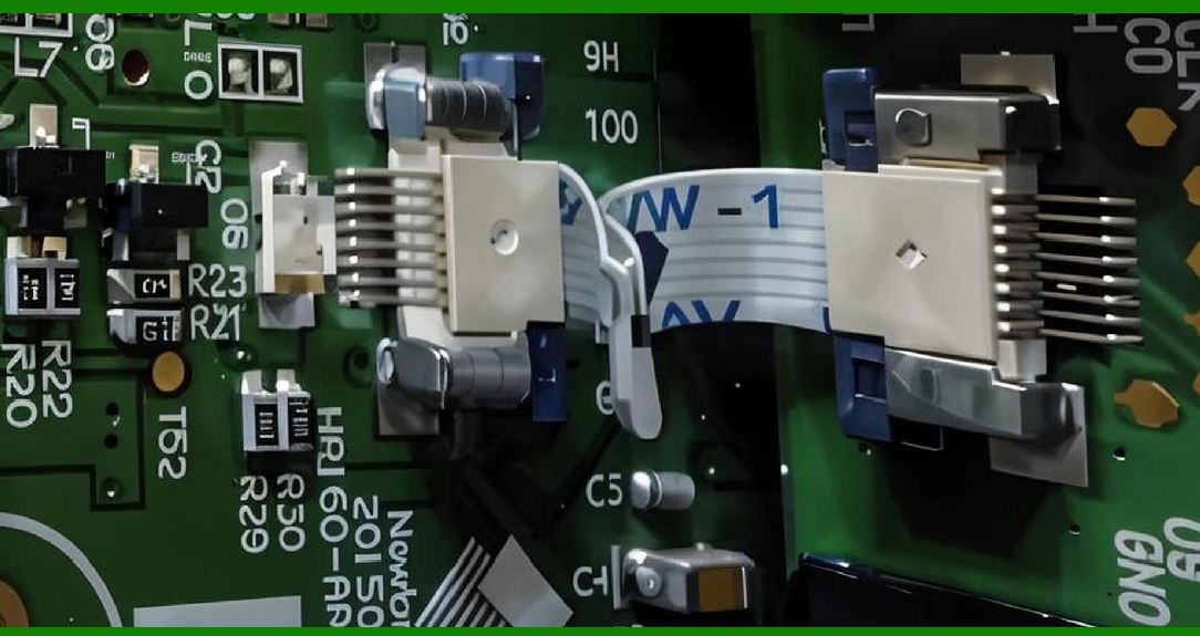
The design of the main circuit board can be broken into several interdependent subsystems: |
Power Supply and Regulation: Provides stable voltage and current to sensitive components. |
Light Source Driver: Manages LEDs or laser diodes, ensuring correct illumination intensity and modulation. |
Sensor Interface: Handles analog signals from photodiodes or digital data streams from imaging sensors. |
Analog Front-End (AFE): Includes amplification, filtering, and noise reduction circuits. |
Digital Processing Core: Typically a microcontroller or embedded processor running decoding algorithms. |
Memory Subsystem: Includes RAM and flash storage for firmware and lookup tables. |
Communication Interfaces: Provides external connectivity (USB, RS-232, Ethernet, Bluetooth, Wi-Fi). |
Auxiliary Circuits: Includes clock generators, oscillators, and reset supervisors. |
PCB Layout and Signal Integrity Design: Ensures electromagnetic compatibility, reduces cross-talk, and optimizes performance. |
|
5. The Role of the Circuit Board in System Integration |
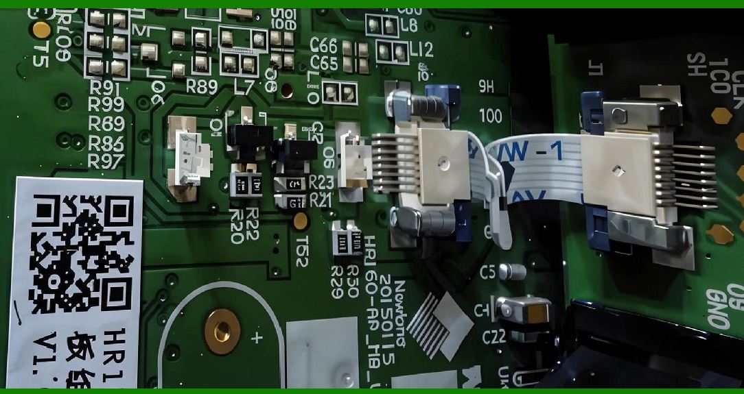
The main circuit board is not merely an electrical medium; it is a system integration platform. It bridges optical components such as lenses and mirrors, electromechanical parts such as scanning mirrors and motors, and digital logic subsystems. The board must handle both analog and digital domains, often requiring careful separation of ground planes, shielding, and power supply isolation to prevent noise coupling. The board must also be robust enough to withstand shocks, vibrations, and environmental challenges such as static discharge or fluctuating ambient light conditions. Its design embodies a balance between theoretical precision and real-world constraints like cost, manufacturability, and size. |
6. Differences Between Laser-Based and Imaging-Based Circuit Designs |
The principle of operation is similar in both technologies, but the circuit design differs in significant ways: |
Laser-Based Scanners rely heavily on analog circuitry for light detection, motor drivers for rotating mirrors, and photodiode conditioning circuits. Their decoding processors primarily analyze one-dimensional signal waveforms. |
Imaging-Based Scanners depend on high-resolution CMOS/CCD sensors, high-speed digital data transfer, advanced image processors, and larger memory banks for handling complex two-dimensional barcodes like QR Code, Data Matrix, or PDF417. |
The choice between these two fundamentally alters the design of the main circuit board, dictating component selection, processing requirements, and power management strategy. |
|
7. Importance of Firmware and Hardware Co-Design |
The circuit board cannot be separated from its embedded firmware. Firmware drives the processor, configures the sensor interface, manages memory usage, and implements barcode decoding logic. Consequently, the board design must anticipate firmware needs: providing enough processing power, allocating memory appropriately, and ensuring the communication interfaces match the application environment. This tight coupling between hardware and software is a defining characteristic of barcode scanner circuit board design. |
8. Introduction to Power Supply in Barcode Scanner Circuit Boards |
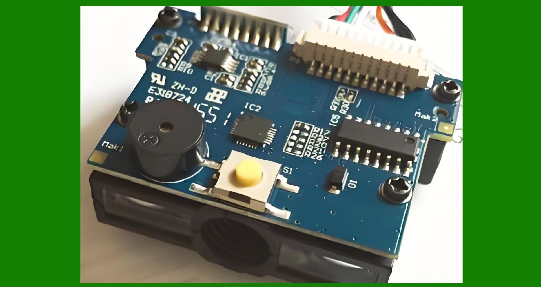
Every electronic system begins with power. The main circuit board of a barcode scanner requires a carefully engineered power subsystem that can accept input power from diverse sources and regulate it into multiple stable supply rails needed by different functional blocks. Barcode scanners are often deployed in varied environments¡ªsome connected directly to POS terminals via USB, some drawing power from RS-232 with external adapters, and others using rechargeable batteries for wireless handheld models. This variability demands a highly adaptable power design capable of supporting both high-current components (like illumination LEDs or laser diodes) and sensitive low-noise circuitry (such as analog front-ends). Without a robust power supply design, even the most sophisticated decoding processor cannot operate reliably. |
|
9. Input Power Sources and Their Implications |
The design begins with identifying the power entry point. Barcode scanners typically use three main categories of input power: |
USB Power (5V): Many handheld or desktop scanners draw power directly from a USB port. While convenient, USB power is limited to 500 mA for USB 2.0 and up to 900 mA for USB 3.0, necessitating strict power budgeting. |
External Power Adapters (5¨C12V): Industrial scanners often use dedicated adapters, offering higher current capability but adding cost and bulk. |
Battery Power (3.7V Lithium-Ion or Lithium-Polymer Cells): Wireless and portable scanners rely on rechargeable batteries, requiring onboard charging circuits, protection ICs, and voltage regulators. |
The circuit board must therefore include input conditioning, surge protection, reverse polarity safeguards, and sometimes hot-plug support. |
10. Voltage Regulation Requirements |
Once the input power is received, it must be converted into multiple voltage rails: |
3.3V: The most common logic voltage for microcontrollers, memory, and digital ICs. |
1.8V or 1.2V: Required by high-performance processors, DSP cores, and modern CMOS sensors. |
5V (retained): Sometimes needed for legacy interfaces, laser diode drivers, or USB communication. |
High Current Rails (up to several hundred mA): For LED arrays or laser drivers, requiring low-ripple regulation. |
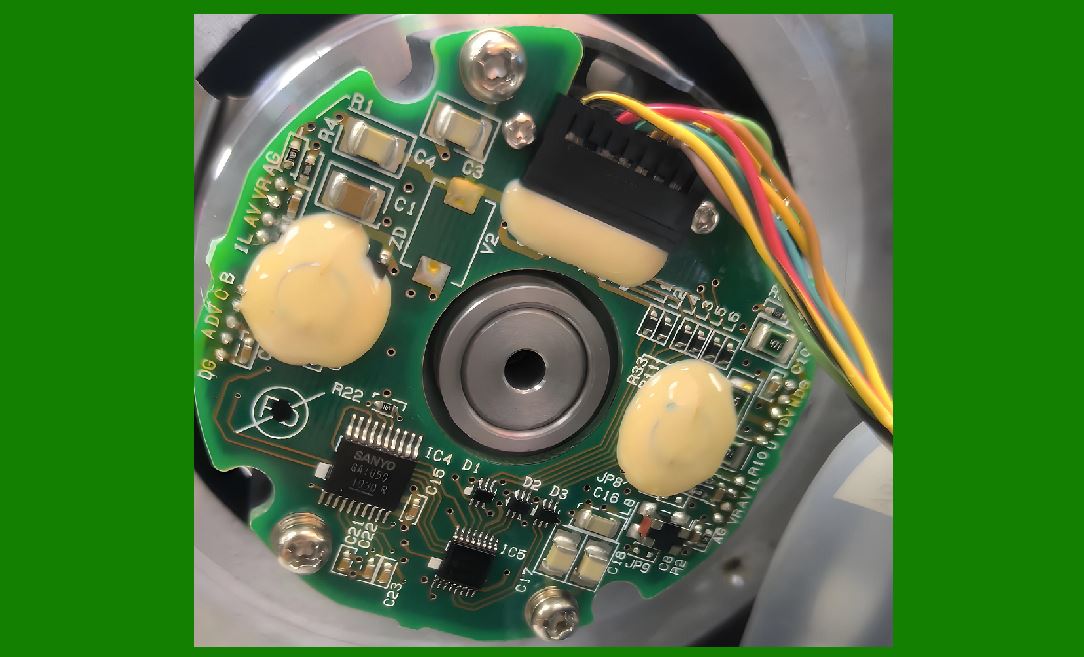
The board uses a combination of switch-mode power supplies (SMPS) for efficiency and low-dropout regulators (LDOs) for noise-sensitive analog circuits. The principle is always to allocate switching regulators to high-current loads, while reserving LDOs for analog sections where power integrity is paramount. |
|
11. Power Management Integrated Circuits (PMICs) |
Modern designs often consolidate power regulation into dedicated PMICs. These ICs integrate multiple buck converters, boost converters, and LDOs into a single package, reducing PCB complexity and improving efficiency. A PMIC also often supports dynamic voltage scaling, which allows the system to reduce core voltage when the processor is idle, thereby extending battery life in portable models. Barcode scanner designers carefully select PMICs based on peak load, efficiency curve, thermal behavior, and EMI performance. |
12. Noise and Ripple Considerations |
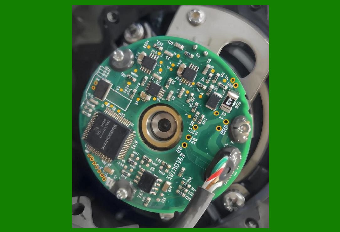
Noise is one of the most critical challenges in power supply design for barcode scanner boards. Since the board must process faint optical signals from photodiodes or CMOS sensors, any ripple or electromagnetic interference (EMI) from switching regulators can directly degrade signal quality. Engineers typically employ: |
LC Filters and Ferrite Beads: To attenuate high-frequency switching noise. |
Separated Ground Planes: Isolating digital ground from analog ground to prevent cross-coupling. |
Decoupling Capacitors: Placed near every IC to stabilize local supply rails. |
Shielding Strategies: Especially important in laser-based scanners, where photodiode signals are highly sensitive. |
The design principle here is maintaining a clean analog supply domain while still leveraging efficient digital regulators. |
|
13. Power Sequencing and Reset Logic |
Complex barcode scanners often require precise power sequencing. For example, the processor¡¯s I/O voltage must not exceed its core voltage during startup; otherwise, it can be permanently damaged. Power sequencing controllers or supervisory ICs enforce the correct order of voltage rail activation. Similarly, reset supervisors ensure that the microcontroller only begins execution after all power rails are stable. These considerations prevent random system failures and increase product reliability in the field. |
14. Thermal Management in Power Design |
Switch-mode regulators, LED drivers, and laser diode drivers all generate significant heat, particularly in compact handheld scanners with limited airflow. Thermal management strategies include: |
Copper Pour Heat Sinks: Enlarged copper areas on the PCB to dissipate heat. |
Thermal Vias: Connecting hot pads to inner or bottom layers for spreading. |
Component Placement: Keeping heat-generating parts away from sensitive analog sections. |
Power Derating: Designing illumination intensity and duty cycle to minimize continuous load. |
The circuit board design integrates thermal modeling into the layout stage to ensure safe operation even in high-temperature retail or warehouse environments. |
|
15. Battery Management for Portable Scanners |
Wireless barcode scanners add an extra layer of complexity through battery management. A battery management system (BMS) on the main board includes: |
Charging Circuit: Handles USB charging or dock charging, typically with constant-current/constant-voltage profiles for Li-ion cells. |
Protection Circuitry: Guards against overcharge, deep discharge, short circuit, and overcurrent. |
Fuel Gauge IC: Reports battery percentage to the microcontroller for display and power-saving strategies. |
This subsystem must be designed to meet regulatory compliance standards (e.g., IEC, UL safety standards for lithium batteries). The integration of BMS into the main circuit board reduces component count and makes handheld scanners more reliable. |
16. Power Budgeting and System-Level Trade-offs |
A final, critical aspect of power supply design is system-level power budgeting. Engineers must account for every subsystem¡¯s consumption: illumination, sensor array, processor, communication module, and idle states. Optimizing duty cycles, implementing sleep modes, and dynamically adjusting LED brightness according to ambient light can drastically improve energy efficiency. This budgeting process often dictates the selection of processor family, memory size, and even communication interface type. In essence, the power supply is not an isolated circuit but a constraint that defines the entire architecture of the scanner¡¯s main board. |
|
17. Introduction to the Analog Front-End (AFE) |
The Analog Front-End (AFE) of a barcode scanner is one of the most delicate and critical subsystems of the main circuit board. Its primary role is to convert weak optical signals, captured by photodiodes or imaging sensors, into clean, conditioned electrical signals suitable for digital processing. Unlike digital circuits, which operate in well-defined voltage logic levels, analog circuits deal with continuously varying signals that are highly susceptible to noise, distortion, and interference. Because barcodes consist of alternating dark and light regions (or in the case of 2D codes, complex patterns), the AFE must be designed to preserve contrast, timing, and edge fidelity with extreme precision. |
18. The Nature of Optical Input Signals |
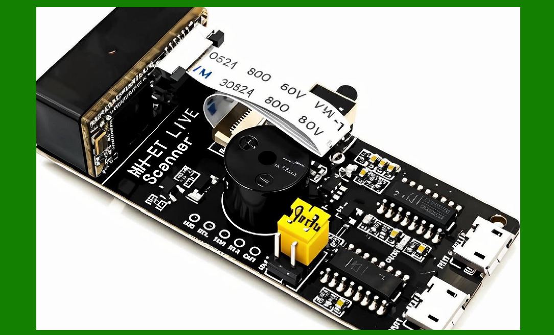
When a barcode scanner illuminates a printed code with a laser beam or LED array, light reflects differently from dark and light regions. Photodiodes or CMOS pixels capture these variations and produce an electrical current proportional to light intensity. In most cases, this signal is extremely weak¡ªoften in the microampere range¡ªand needs amplification before further processing. Complicating matters, ambient light from fluorescent lamps, sunlight, or display screens introduces unwanted background signals. The AFE must therefore extract meaningful barcode information from a noisy, low-level optical input. |
|
19. Photodiode Interfacing |
In laser-based scanners, the photodiode is the primary sensor. It converts photons into current via the photoelectric effect. The circuit board typically integrates the photodiode into a transimpedance amplifier (TIA) configuration. |
Principle: A TIA converts the tiny photocurrent into a proportional voltage. |
Design Requirements: The amplifier must have ultra-low input bias current, low noise, and a carefully chosen feedback resistor to set the gain. |
Challenges: High gain increases sensitivity but also amplifies noise; too low gain risks losing barcode contrast. |
Designers often include switchable gain stages or automatic gain control (AGC) to adapt to different scanning environments. |
20. Signal Amplification and Conditioning |
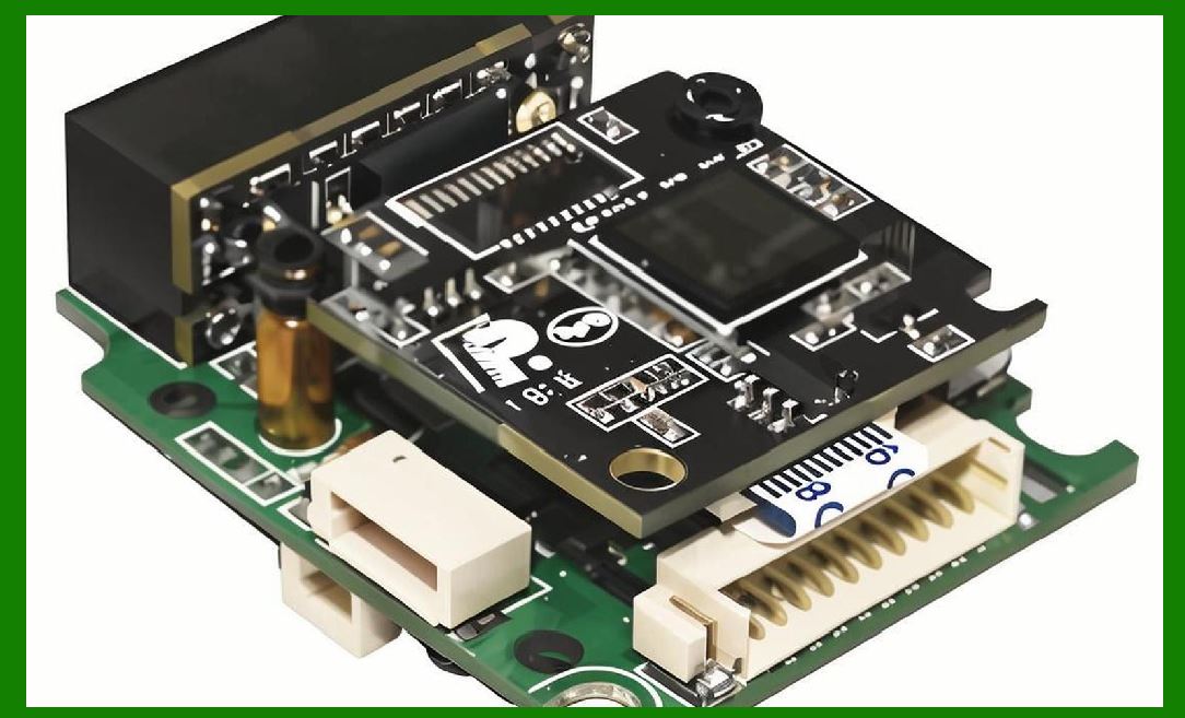
Once the signal is converted to voltage, it undergoes further amplification. This is typically achieved using operational amplifiers configured in non-inverting or differential modes. The goal is to bring the signal into a range suitable for an analog-to-digital converter (ADC) or comparator while minimizing distortion. Key techniques include: |
Low-Noise Amplifiers (LNAs): To prevent noise floor elevation. |
Programmable Gain Amplifiers (PGAs): Allowing firmware-controlled adjustment of sensitivity. |
AC Coupling: Filtering out DC offset caused by ambient light. |
High-Pass Filtering: Removing slow variations due to uneven illumination or reflections. |
The amplified signal must preserve the fast rise and fall times of transitions between black and white bars, since decoding depends on accurate edge detection. |
|
21. Noise Sources and Suppression Techniques |
Noise is a persistent challenge in AFE design. Sources include thermal noise in resistors, shot noise in photodiodes, and electromagnetic interference from switching power supplies or wireless transmitters. To mitigate these: |
Shielding and Grounding: The photodiode and amplifier are often enclosed in metal shielding. |
PCB Layout Practices: Short traces, guard rings around sensitive inputs, and separation of analog and digital ground planes reduce coupling. |
Filtering: Carefully tuned RC filters suppress high-frequency noise while preserving barcode edge detail. |
Differential Signaling: In some designs, the AFE outputs differential signals to reject common-mode noise. |
22. Ambient Light Rejection |
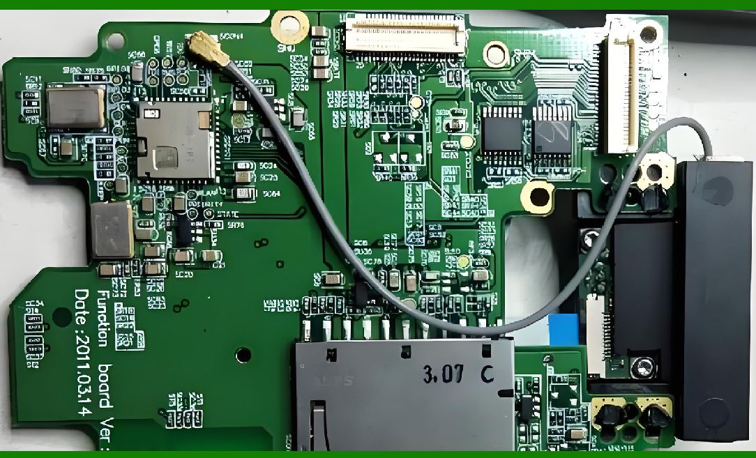
Barcode scanners frequently operate in brightly lit retail stores or warehouses. Direct sunlight or fluorescent flicker can swamp the sensor. Engineers implement multiple strategies: |
Optical Bandpass Filters: Positioned in front of the photodiode, allowing only laser or LED wavelengths to pass. |
Electronic Synchronous Detection: In laser scanners, the laser beam is modulated at a known frequency, and the AFE includes a lock-in amplifier tuned to that frequency. This rejects any signal not matching the modulation. |
Digital Baseline Correction: Firmware can subtract constant offsets introduced by ambient light. |
This combination ensures reliable scanning under diverse conditions. |
|
23. Analog-to-Digital Conversion (ADC) |
Once conditioned, the analog signal must be digitized for processing by the microcontroller or DSP. ADC requirements vary by scanner type: |
Laser-Based Scanners: Typically use medium-speed ADCs (1¨C5 MS/s, 8¨C10 bit resolution) since the signal is one-dimensional. |
Imaging-Based Scanners: Require high-speed, high-resolution ADCs (tens of MS/s, 10¨C14 bit resolution) to capture 2D images. |
The ADC¡¯s dynamic range must be wide enough to capture faint reflections while avoiding saturation from bright reflections. Oversampling and digital filtering are often used to further enhance signal quality. |
24. Automatic Gain Control (AGC) and Adaptive Signal Processing |
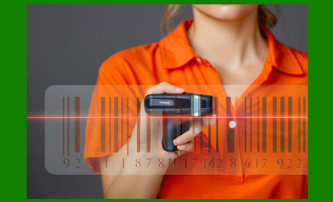
Modern barcode scanners incorporate AGC loops within the AFE. The principle is simple: if the incoming signal is too weak, the system increases gain; if it is too strong, gain is reduced. This ensures consistent signal amplitude regardless of barcode print quality, distance, or surface reflectivity. Implementation typically involves: |
A feedback loop from the ADC output to the amplifier gain setting. |
Algorithms running on the microcontroller to monitor signal statistics and adjust gain dynamically. |
Integration with LED brightness control for balanced performance. |
This closed-loop approach allows scanners to handle poor print quality codes that older designs might fail to read. |
|
25. Edge Detection and Comparator Circuits |
In simpler, low-cost barcode scanners, rather than digitizing the entire analog waveform, the AFE uses comparator circuits to directly detect transitions between dark and light regions. These comparators convert the analog waveform into a square wave representing barcode stripes. While efficient, this method lacks the flexibility of full digital decoding and struggles with noisy or degraded barcodes. Nevertheless, it remains relevant in entry-level designs where cost and power consumption outweigh versatility. |
26. AFE Variations Between 1D and 2D Scanners |
The choice between one-dimensional and two-dimensional scanning fundamentally alters AFE design: |
1D Laser Scanners: Rely heavily on TIAs, AGC, and comparators, with relatively simple ADC requirements. |
2D Imaging Scanners: Integrate complex CMOS sensor interfaces, column-parallel ADCs, and digital timing control. In many cases, the imaging sensor includes its own AFE integrated on-chip, simplifying the main board design but raising firmware complexity. |
The shift from analog-dominant to digital-dominant AFEs marks a major evolutionary step in barcode scanner technology. |
|
27. Testing and Calibration of the AFE |
No AFE design is complete without rigorous testing and calibration. Manufacturing calibration routines typically include: |
Dark Calibration: Measuring baseline noise with the light source off. |
White Calibration: Scanning a known white target to normalize maximum signal. |
Linearity Tests: Ensuring that intermediate gray levels correspond to expected signal amplitudes. |
Temperature Compensation: Adjusting gain and offset values for consistent performance across operating ranges. |
These calibration parameters are often stored in EEPROM or flash memory on the main circuit board and applied automatically during operation. |
28. The AFE as the Foundation of Reliable Scanning |
The AFE is arguably the most critical determinant of scanning performance. While decoding algorithms and communication interfaces can be refined with software updates, the quality of the raw signal is fixed by the analog circuitry. Poorly designed AFEs lead to frequent misreads, slow decoding, and high power consumption. Conversely, a carefully engineered AFE with robust noise rejection, adaptive gain, and clean ADC conversion allows the rest of the system to operate efficiently and reliably. Thus, in the hierarchy of the main circuit board, the AFE forms the foundation upon which digital processing and system integration are built. |

|
29. Introduction to the Digital Core |
At the heart of every barcode scanner¡¯s main circuit board lies the digital processing core¡ªthe subsystem responsible for interpreting signals, applying decoding algorithms, managing device operation, and communicating with external systems. If the AFE can be compared to the eyes and ears of the scanner, the digital core is its brain. It transforms conditioned signals into meaningful alphanumeric data, manages firmware execution, controls illumination and scanning mechanisms, and ensures that the final decoded result is transmitted reliably to a host system. |
The design of the digital processing core is perhaps the most versatile aspect of the circuit board. While optical components and AFEs are constrained by physics, the digital core can evolve with advances in microcontrollers, embedded processors, and software algorithms. This adaptability explains why scanners from the 1980s and those of today differ dramatically in processing capability even though their optical principles remain similar. |
30. Processor Selection Criteria |
The choice of processor determines the capabilities of the barcode scanner. Engineers weigh several factors when selecting a digital core: |
Processing Power: Needed for real-time decoding, especially for 2D codes. Early 1D scanners used simple 8-bit microcontrollers, but modern 2D scanners often require 32-bit ARM Cortex-M or even Cortex-A processors. |
Clock Speed: Must balance performance with power consumption. For handheld devices, power efficiency is as important as speed. |
Integrated Peripherals: ADC interfaces, PWM generators, UARTs, USB controllers, and SPI/I2C buses reduce the need for external components. |
Cost and Availability: The processor must be cost-effective for mass production and available in stable supply. |
Firmware Ecosystem: Availability of compilers, development tools, and libraries accelerates firmware development. |
These considerations dictate whether a scanner can decode only basic 1D barcodes or handle complex 2D symbologies under poor print conditions. |

|
31. Microcontrollers vs. Microprocessors in Scanners |
Barcode scanners use two main categories of digital cores: |
Microcontrollers (MCUs): These are single-chip solutions integrating CPU, RAM, flash memory, and peripherals. They are favored in cost-sensitive, power-efficient designs such as handheld 1D scanners. |
Microprocessors (MPUs): These provide higher performance and require external memory and peripherals. They are found in advanced 2D scanners or multifunctional devices that combine scanning with imaging, networking, or touchscreen interfaces. |
For example, a basic supermarket scanner may use an 8-bit MCU running at a few MHz, while an industrial-grade 2D scanner might employ a 32-bit ARM MPU with DDR memory and a dedicated GPU-like co-processor for image decoding. |
32. Memory Subsystems and Their Role |
A scanner¡¯s memory hierarchy directly influences its performance: |
Flash Memory: Stores firmware, calibration parameters, and decoding libraries. Non-volatile storage ensures that the scanner retains functionality even after power cycles. |
SRAM: Provides fast temporary storage for signal buffers, image frames, and intermediate decoding results. |
EEPROM: Sometimes used for storing configuration parameters and device IDs. |
External DRAM: Required in advanced 2D scanners to handle image frames, which may reach several megapixels in size. |
Memory capacity is carefully balanced: too little memory hampers decoding, while excessive memory increases cost and power consumption. |

|
33. Clocking and Timing Control |
Accurate timing is essential for both analog sampling and digital decoding. The processor relies on crystal oscillators or MEMS oscillators to provide precise system clocks. For imaging scanners, additional timing signals synchronize the sensor¡¯s exposure, line scanning, and frame capture. Jitter and clock instability can cause decoding errors, especially in high-speed scanners where bars must be sampled at exact intervals. Therefore, the main circuit board often includes: |
High-Stability Quartz Oscillators: For primary system clocks. |
Phase-Locked Loops (PLLs): To generate multiple clock domains from a single source. |
Low-Power Clock Sources: For standby and sleep modes. |
34. Firmware and Embedded Software Integration |
The processor is only as powerful as the firmware it runs. Barcode scanner firmware is a sophisticated piece of embedded software that performs multiple roles: |
Initialization: Configures power sequencing, interfaces, and sensor settings at startup. |
Signal Acquisition: Collects digitized waveforms or image data from the AFE or sensor. |
Decoding Algorithms: Identifies symbology type (e.g., Code 128, QR Code, Data Matrix) and applies pattern recognition, error correction, and checksum validation. |
Device Control: Manages illumination, beeper feedback, and user buttons. |
Communication Protocols: Formats decoded data and transmits it via USB, RS-232, Bluetooth, or Wi-Fi. |
Firmware updates often extend a scanner¡¯s life by adding support for new symbologies or improving error correction. |

|
35. Barcode Decoding Algorithms |
The processor¡¯s main computational task is decoding. This process involves several steps: |
For 1D Barcodes: |
Edge detection and timing measurement. |
Conversion of wide and narrow bars into binary sequences. |
Symbology-specific parsing and checksum validation. |
For 2D Barcodes: |
Image acquisition and binarization (converting grayscale to black/white). |
Finder pattern detection (e.g., the three squares in QR Code). |
Grid alignment and perspective correction. |
Error correction decoding, often using Reed-Solomon or BCH algorithms. |
The complexity of these algorithms explains why higher processing power is required for 2D codes compared to 1D. |
36. Error Correction and Redundancy |
Modern barcodes are designed with redundancy and error correction, but implementing these requires computational resources. The digital core executes algorithms that can reconstruct missing or distorted parts of the code. For instance, QR Codes can tolerate up to 30% damage, but this places heavy demands on the processor. The firmware must strike a balance between robustness and speed¡ªdecoding quickly in ideal conditions, but applying full error correction in difficult cases. |

|
37. Real-Time Constraints |
One of the defining challenges of scanner processor design is the requirement for real-time performance. Customers expect instant results¡ªwhen they scan a product at checkout, the code must decode within a fraction of a second. This means the processor and firmware must operate under strict timing constraints: |
Low Latency: From image capture to decoded data, typically under 200 ms. |
Deterministic Performance: Consistent results even under load. |
Interrupt Handling: Fast response to trigger presses, communication requests, and sensor events. |
The circuit board design ensures that processor cycles are not wasted, often incorporating hardware accelerators for checksum calculations or image processing. |
38. Hardware Acceleration and DSP Cores |
Some advanced scanners integrate Digital Signal Processors (DSPs) or hardware accelerators for tasks such as: |
Convolution and filtering in image processing. |
Fast Fourier Transform (FFT) for analyzing frequency components. |
Error correction algorithms. |
CRC and checksum calculations. |
These specialized hardware blocks reduce the load on the main CPU and allow faster decoding without increasing power consumption significantly. |
|
39. Security Features in the Digital Core |
As barcode scanners are increasingly network-connected, security becomes an important design consideration. The digital processing core may include: |
Secure Bootloaders: Ensuring that only authenticated firmware can run. |
Encryption Engines: Protecting transmitted data, particularly in healthcare and payment systems. |
Tamper Detection: Monitoring for unauthorized modification of firmware or hardware. |
These measures prevent malicious attacks, such as code injection via communication interfaces. |
40. Digital Core Power Management |
Given the central role of the digital core, its power consumption is critical. Techniques include: |
Dynamic Voltage and Frequency Scaling (DVFS): Adjusting processor speed based on workload. |
Sleep and Standby Modes: Reducing consumption when idle. |
Peripheral Gating: Powering down unused interfaces. |
Firmware plays a central role in orchestrating these modes, ensuring balance between performance and energy efficiency. |
|
41. Evolution of Processing Cores in Scanners |
The progression of digital cores mirrors broader trends in embedded systems: |
1970s¨C1980s: Simple analog comparators with minimal microcontroller assistance. |
1990s: 8-bit microcontrollers with fixed-function decoders. |
2000s: 16-bit and 32-bit MCUs, supporting 2D symbologies and USB connectivity. |
2010s¨CPresent: ARM Cortex processors, dedicated image processors, and AI-assisted decoding for blurred or damaged codes. |
This evolution underscores the digital core¡¯s adaptability and central role in advancing barcode scanning technology. |
42. Integration of the Digital Core with the Rest of the Board |
The processor does not work in isolation. It is tightly integrated with: |
The AFE, from which it receives clean digitized data. |
The power supply subsystem, which provides stable rails and sequencing. |
The communication interfaces, which transmit decoded results. |
The illumination and optics controls, which it regulates for optimal capture. |
PCB layout must ensure short, interference-free connections between these subsystems, while firmware ensures synchronized operation. |

|
43. The Digital Core as the Central Intelligence |
Ultimately, the digital processing core transforms the barcode scanner from a passive optical reader into an intelligent data acquisition system. It is where analog physics meets digital logic, where photons become bytes, and where engineering precision meets user experience. A well-designed digital core ensures that the scanner is not only functional but also fast, reliable, and future-proof. |
 cs@easiersoft.com