1. Introduction to Error Correction in 2D Codes |
1.1 Why Error Correction Exists in 2D Codes |
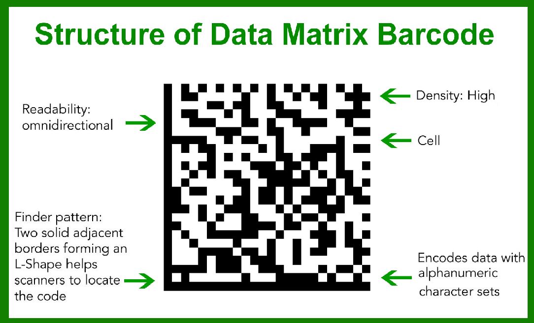
Error correction is a foundational capability that distinguishes modern two-dimensional (2D) barcodes from traditional one-dimensional (1D) barcodes. In a physical environment, printed symbols are rarely preserved in perfect condition. They are subject to abrasion, partial occlusion, smudging, low contrast, distortion, curvature, lighting variation, and sensor noise. Error correction exists to ensure that the encoded data can still be recovered accurately even when portions of the symbol are damaged or unreadable. |
In 1D barcodes, redundancy is minimal and error tolerance is limited. Most linear barcodes rely on check digits primarily for error detection rather than correction. If a significant portion of a 1D barcode is damaged, decoding typically fails entirely. In contrast, 2D codes are explicitly designed with mathematical redundancy, allowing missing or corrupted modules to be reconstructed. |
Error correction level settings represent a configurable trade-off between data capacity and robustness. Increasing the error correction level reduces usable data capacity but increases resistance to damage. Decreasing it allows more data to be stored but reduces fault tolerance. |
|
1.2 Definition of Error Correction Level |
An error correction level is a predefined or configurable parameter that determines how much redundant information is embedded into a 2D code to allow recovery from errors. This redundancy is not arbitrary; it is generated using formal error correction algorithms, most commonly based on Reed-solomon coding, though other mechanisms also exist depending on the symbology. |
The error correction level controls: |
1. The proportion of error correction codewords relative to data codewords |
2. The maximum number of symbol errors that can be corrected |
3. The symbol resilience to physical damage, distortion, or noise |
4. The maximum effective data density for a given symbol size |
1.3 Error Detection Versus Error Correction |
Error detection and error correction are related but distinct concepts. |
Error detection refers to the ability of a decoding system to identify that an error has occurred. This is often achieved using parity bits, checksums, or cyclic redundancy checks. Detection alone does not permit recovery; it merely signals failure. |
Error correction goes further. It allows the decoder to reconstruct the original data even when errors are present, without requiring retransmission or rescanning. 2D codes prioritize error correction rather than simple detection, making them suitable for printed, static media. |
|
2. Historical Development of Error Correction in 2D Codes |
2.1 Origins in Information Theory |
The theoretical foundation of error correction originates in information theory, particularly the work of Claude Shannon in the mid-20th century. Shannon demonstrated that reliable communication over noisy channels is possible if redundancy is introduced in a mathematically optimal way. |
Early practical error correction schemes were developed for telecommunications, magnetic storage, and optical media. These same mathematical principles were later applied to machine-readable symbols. |
2.2 Transition from Linear to Matrix Codes |
As barcode technology evolved from linear to matrix formats, the available symbol area increased dramatically. This made it feasible to incorporate significant redundancy without excessively increasing symbol size. |
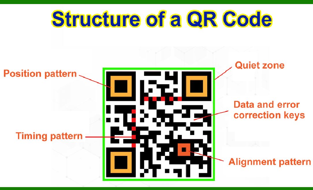
Early 2D codes, such as PDF417, already incorporated error correction, but matrix codes like Data Matrix and QR Code pushed this further by embedding error correction uniformly across both dimensions of the symbol. |
2.3 Standardization of Error Correction Levels |
Different symbologies adopted different approaches to error correction configuration: |
1. Fixed error correction levels, determined by symbol size |
2. Discrete selectable levels, offering several predefined robustness options |
3. Continuous or scalable error correction ratios |
Standardization bodies formalized these approaches to ensure interoperability between encoders and decoders from different vendors. |

|
3. Mathematical Foundations of Error Correction |
3.1 Codewords and Symbols |
In 2D codes, data is not encoded directly as raw bits. Instead, information is grouped into codewords, which are fixed-length units of data, typically 8 bits or more. |
A symbol consists of: |
1. Data codewords, representing the actual payload |
2. Error correction codewords, representing redundancy |
The total number of codewords is determined by the symbol size and version. |
3.2 Reed-Solomon Coding Overview |
Reed-Solomon (RS) codes are the most widely used error correction method in 2D barcodes. They operate over finite fields and are particularly effective at correcting burst errors, which are common in printed symbols where contiguous areas may be damaged. |
Key properties of Reed-Solomon codes include: |
1. They are block-based rather than bit-based |
2. They can correct both errors and erasures |
3. Correction capability is directly proportional to the number of redundant symbols |
If a code contains N error correction codewords, it can typically correct up to N/2 erroneous codewords, or up to N missing (erased) codewords. |
3.3 Errors Versus Erasures in 2D Codes |
An important distinction in decoding is between errors and erasures. |
An error is a codeword that is read incorrectly but appears valid. |
An erasure is a codeword location that the decoder knows is unreadable or missing. |
In printed barcodes, erasures occur when modules are completely destroyed or unreadable. Reed-Solomon codes are especially powerful in this scenario because erasures are easier to correct than unknown errors. |
3.4 Spatial Distribution of Error Correction Codewords |
In well-designed 2D codes, error correction codewords are interleaved spatially with data codewords. This ensures that localized damage affects both data and error correction uniformly rather than destroying all redundancy in one area. |
The interleaving strategy is a critical aspect of error correction effectiveness and is tightly coupled with the symbol layout rules. |

|
4. Concept of Error Correction Levels |
4.1 Discrete Versus Continuous Levels |
Error correction levels may be discrete or continuous depending on the symbology. |
Discrete levels define a small set of named options, such as 'low,'mediumh,or 'high'.Each level corresponds to a fixed ratio of error correction codewords to data codewords. |
Continuous levels allow more granular control, often by specifying an explicit number or percentage of error correction codewords. |
4.2 Trade-Off Between Capacity and Robustness |
Increasing the error correction level always reduces data capacity for a given symbol size. This trade-off is unavoidable due to the fixed physical area of the symbol. |
At low error correction levels: |
1. Data capacity is maximized |
2. Symbols are smaller for the same data |
3. Tolerance to damage is limited |
At high error correction levels: |
1. Data capacity is reduced |
2. Symbols are larger or store less data |
3. Tolerance to damage is significantly improved |
4.3 Practical Interpretation of Error Correction Percentages |
When an error correction level is described as being able to recover a certain percentage of damage, this does not mean that any arbitrary pattern of damage covering that percentage will be recoverable. |
Instead, it means that under typical assumptions of random or moderately clustered damage, the decoder can reconstruct the original data if up to that proportion of codewords are missing or corrupted. |

|
5. Relationship Between Symbol Size and Error Correction |
5.1 Fixed-Size Symbols |
Some 2D codes have fixed symbol sizes where error correction levels are predetermined. In these cases, increasing data content forces the use of a larger symbol version, which automatically increases the total number of error correction codewords. |
5.2 Variable-Size Symbols |
Other symbologies allow the same symbol size to support multiple error correction levels. In these cases, the encoder explicitly chooses how many codewords are allocated to redundancy versus payload. |
5.3 Minimum Error Correction Requirements |
Standards often define minimum error correction requirements to ensure basic readability under normal conditions. Encoders may not be allowed to reduce error correction below this threshold. |
|
6. Environmental Factors Influencing Error Correction Level Choice |
6.1 Print Quality |
Low-resolution printers, ink spread, and inconsistent contrast increase the probability of decoding errors. Higher error correction levels compensate for these issues at the cost of symbol size. |
6.2 Surface Material |
Rough, reflective, curved, or flexible surfaces distort printed modules. Error correction helps recover data when geometric distortions cause misreads. |
6.3 Scanning Conditions |
Lighting variability, camera quality, motion blur, and scanning distance all affect decoding reliability. Symbols intended for camera-based scanning often require higher error correction than those scanned by fixed industrial readers. |

|
7. Human and Operational Factors |
7.1 User Handling |
Symbols that may be scratched, folded, or partially covered during handling benefit from higher error correction. |
7.2 Lifecycle Duration |
Long-term labeling applications, such as asset tags or compliance labels, require higher robustness than short-term logistics labels. |
7.3 Regulatory and Safety Considerations |
In regulated industries, failure to decode a symbol may have legal or safety consequences. In such cases, higher error correction is often mandated or strongly recommended. |
|
8. Error Correction as a Design Parameter |
8.1 Encoder Responsibility |
The encoder is responsible for selecting an appropriate error correction level based on application requirements. This decision cannot be deferred to the decoder. |
8.2 Decoder Transparency |
From the user perspective, error correction is typically invisible. Decoders automatically attempt to recover data without indicating how much correction was required. |
8.3 Misconceptions About maximumError Correction |
Choosing the highest possible error correction level is not always optimal. Excessive redundancy may increase symbol size beyond practical limits or reduce scanning reliability due to overly dense module patterns. |

|
9. Overview of Error Correction Across Major 2D Code Families |
9.1 Matrix Codes |
Matrix codes rely heavily on block-based error correction and spatial interleaving. Error correction levels are often a defining feature of the symbology. |
9.2 Stacked Codes |
Stacked codes combine linear elements with 2D structure. Their error correction mechanisms differ in structure and configuration options. |
9.3 Proprietary and Specialized Codes |
Some specialized codes use custom or hybrid error correction schemes tailored to specific scanning environments or data types. |

|
10. Scope of Subsequent Parts |
This first part has established the conceptual and theoretical foundation for understanding error correction level settings in 2D codes. |
In the next parts, the discussion will expand into: |
1. Detailed analysis of error correction level implementations in specific 2D symbologies |
2. Deep exploration of configurable versus fixed error correction strategies |
3. Practical encoding scenarios and decision frameworks |
4. Interaction between error correction and symbol layout, masking, and modulation |
5. Performance limits, failure modes, and real-world case studies |
 cs@easiersoft.com