Part 3: Mathematical Behavior, Damage Models, and Symbol-Level Interactions |
19. Mathematical Interpretation of Error Correction Capacity |
19.1 Codeword-Based Correction Limits |
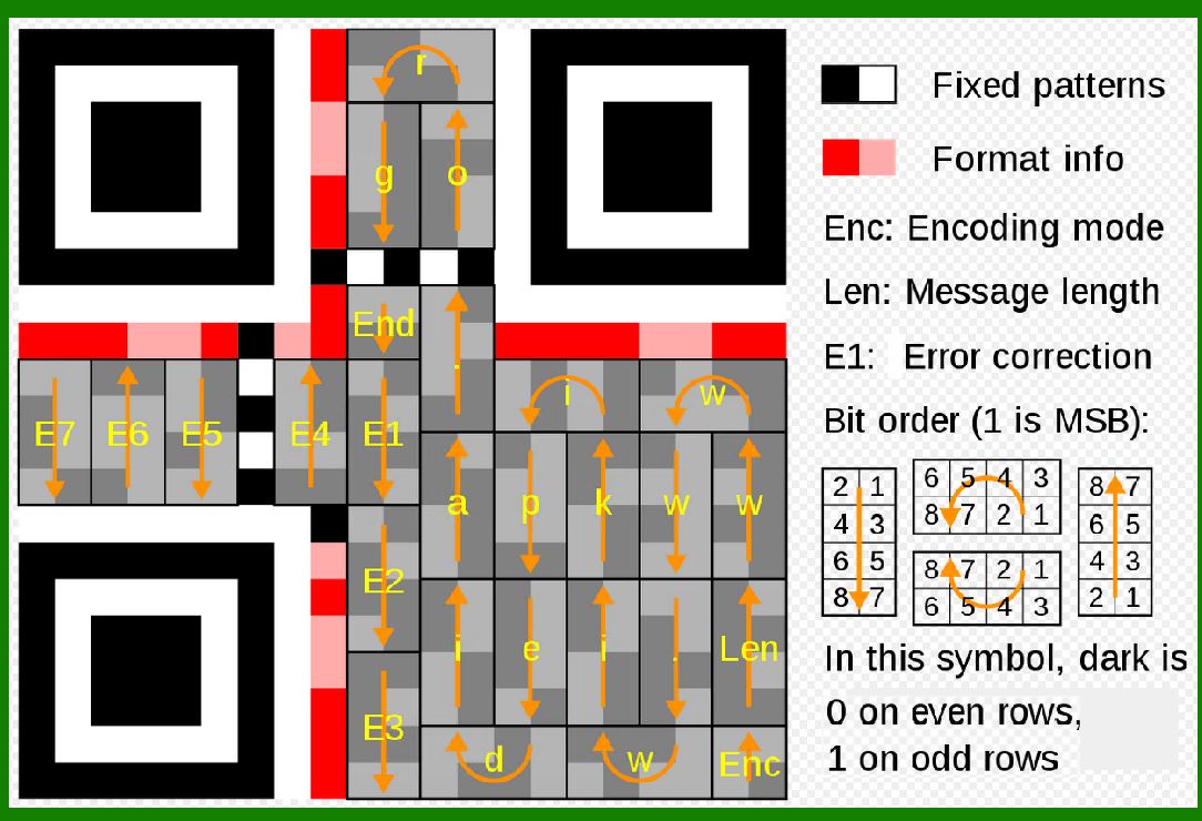
In most 2D codes, error correction capability is expressed in terms of codewords rather than individual modules or bits. This distinction is crucial for understanding real-world performance. |
A codeword represents a group of bits that are treated as a single unit by the error correction algorithm. When a module-level error occurs, it may or may not corrupt the entire codeword depending on how the modules map to codewords spatially. |
Theoretical correction limits are often described using idealized assumptions, such as random distribution of errors. In practice, errors tend to cluster, making spatial distribution and interleaving just as important as raw correction capacity. |
|
19.2 Error Correction Boundaries and Decoding Failure |
Error correction algorithms operate within strict mathematical limits. Once the number of erroneous or erased codewords exceeds the correction capability, decoding fails abruptly rather than degrading gracefully. |
This 'cliff effect' means that a symbol may decode perfectly under substantial damage, then suddenly become unreadable when a small additional area is compromised. |
Understanding this behavior is essential when selecting error correction levels for safety-critical or mission-critical applications. |
|
19.3 Error Versus Erasure Dominance in Printed Symbols |
In printed 2D codes, erasures are more common than random errors. Smudges, scratches, and occlusions often make modules unreadable rather than incorrectly read. |
Error correction algorithms perform significantly better when erasures dominate, because the decoder knows which positions are unreliable and can focus on reconstructing missing values. |
This explains why many 2D codes perform better in practice than their theoretical worst-case correction limits would suggest. |

|
20. Damage Models and Their Impact on Error Correction |
20.1 Random Noise Damage |
Random noise damage occurs when small, isolated modules are corrupted across the symbol. This type of damage is common in low-contrast printing or sensor noise. |
Random noise is generally well handled by error correction, especially when codewords are interleaved. Higher error correction levels provide greater tolerance, but even moderate levels can perform well under this model. |
20.2 Localized Block Damage |
Localized damage occurs when a contiguous region of the symbol is destroyed or obscured. Examples include stickers placed over a code or scratches from sharp objects. |
This damage model is more challenging for error correction because entire groups of adjacent codewords may be lost simultaneously. |
Interleaving strategies are specifically designed to mitigate this risk by ensuring that adjacent modules belong to different codewords or blocks. |
20.3 Edge Damage Versus Central Damage |
Damage near the edges of a symbol often has different implications than damage near the center. |
Edge damage may affect quiet zones, timing patterns, or finder structures, potentially preventing symbol detection before error correction can even be applied. |
Central damage is often more recoverable, particularly in symbols with distributed error correction and redundant alignment patterns. |
20.4 Directional Damage and Print Artifacts |
Certain printing or marking processes introduce directional artifacts, such as streaks, banding, or compression in one axis. |
Error correction performance depends on how codewords are mapped across rows and columns. Symbols with balanced two-dimensional interleaving are more resistant to directional damage than those with predominantly linear structures. |

|
21. Interleaving Strategies and Their Role in Error Correction |
21.1 Purpose of Interleaving |
Interleaving rearranges the spatial placement of codewords so that adjacent modules do not belong to the same codeword or error correction block. |
The primary goal is to convert localized damage into distributed errors at the codeword level, which error correction algorithms can handle more effectively. |
21.2 Block Interleaving Versus Symbol-Wide Interleaving |
Some symbologies use block-level interleaving, where codewords are interleaved within predefined blocks. |
Others use symbol-wide interleaving, distributing codewords across the entire symbol area. |
Symbol-wide interleaving generally provides better resilience to large contiguous damage but may increase decoding complexity. |
21.3 Trade-Offs in Interleaving Design |
Aggressive interleaving improves robustness but can complicate decoding and increase sensitivity to alignment errors. |
Designers must balance interleaving depth against practical considerations such as decoder processing power and real-time scanning requirements. |

|
22. Masking, Modulation, and Error Correction Interaction |
22.1 Purpose of Masking |
Masking is used in some 2D codes to avoid problematic patterns, such as large areas of uniform color or repeating structures that confuse scanners. |
Masking changes the appearance of the symbol without altering the underlying data or error correction codewords. |
22.2 Mask Selection and Error Distribution |
Different masks produce different spatial distributions of black and white modules. This indirectly affects how damage impacts codewords. |
A well-chosen mask can reduce the likelihood that damage will disproportionately affect specific codewords or blocks. |
22.3 Modulation Schemes and Error Sensitivity |
Some 2D codes use multiple module states or color modulation. These schemes may be more sensitive to printing variations and lighting conditions. |
Higher error correction levels are often required to compensate for the increased risk of misinterpretation in such systems. |

|
23. Functional Patterns and Their Relationship to Error Correction |
23.1 Finder Patterns and Error Correction Limits |
Finder patterns, alignment patterns, and timing patterns are essential for symbol detection and grid reconstruction. Damage to these elements can prevent decoding entirely, regardless of error correction level. |
This means that error correction does not protect the entire symbol equally. Certain areas are functionally critical and must be preserved. |
23.2 Redundancy in Functional Patterns |
Some symbologies include multiple alignment patterns or redundant timing structures to improve resilience. |
While these are not error correction codewords in the mathematical sense, they play a similar role by increasing tolerance to damage. |
23.3 Design Implications for Logo Placement |
When modifying symbols for branding or aesthetic purposes, it is critical to avoid functional patterns. High error correction levels cannot compensate for loss of essential structural elements. |

|
24. Error Correction and Module Size |
24.1 Relationship Between Module Size and Error Rate |
Smaller modules increase data density but are more susceptible to printing defects and scanning noise. |
Higher error correction levels can mitigate some of these risks but cannot fully compensate for modules that are below the practical resolution limit of the printing and scanning system. |
24.2 Effective Versus Theoretical Correction |
Theoretical correction capability assumes ideal detection of module states. In practice, module size, contrast, and edge sharpness determine how reliably modules can be classified. |
Error correction is most effective when module-level detection is reasonably accurate. |

|
25. Symbol Orientation, Perspective, and Distortion |
25.1 Perspective Distortion Effects |
Camera-based scanning introduces perspective distortion, especially at oblique angles. |
Error correction helps recover data from modules that are partially distorted, but severe geometric distortion may prevent accurate grid reconstruction. |
25.2 Rotation and Skew |
Most 2D codes are rotationally invariant. Error correction supports recovery after rotation, but alignment patterns must still be detectable. |
Skew combined with low error correction can lead to decoding failure even when a large portion of the symbol is intact. |

|
26. Error Correction Failure Modes |
26.1 Silent Failure Versus Explicit Failure |
In most implementations, error correction failure results in explicit decoding failure rather than incorrect data output. |
This is a deliberate design choice to prevent the use of corrupted data in critical applications. |
26.2 Partial Data Recovery Is Not Supported |
Unlike some communication protocols, 2D codes do not support partial data recovery. Either the entire payload is recovered correctly, or decoding fails. |
This binary outcome emphasizes the importance of selecting appropriate error correction levels. |

|
27. Overengineering Error Correction |
27.1 Diminishing Returns |
Beyond a certain point, increasing error correction yields diminishing returns. Extremely high redundancy may not significantly improve real-world performance if other factors dominate. |
27.2 Symbol Complexity and Scanning Reliability |
High error correction often results in denser symbols with more modules. This can increase decoding difficulty, especially for low-quality cameras. |
Thus, maximum error correction is not always the optimal choice. |

|
28. Summary of Part 3 |
This part has explored the deep mathematical and structural behavior of error correction levels in 2D codes. It has shown that error correction effectiveness depends not only on the amount of redundancy but also on spatial distribution, interleaving, masking, module size, and damage patterns. |
 cs@easiersoft.com