1. Introduction to RFID Technology |
Radio Frequency Identification (RFID) is a wireless communication technology used for identification and tracking of objects. RFID systems are composed of three main components: the RFID tag, the RFID reader, and the communication network that links them. The RFID tag itself is a small electronic device that consists of a microchip and an antenna. It stores information that can be retrieved when the tag is interrogated by an RFID reader. |
|
2. Basic Components of an RFID Tag |
An RFID tag consists of several key components that work together to facilitate data exchange: |
Microchip (Integrated Circuit): This component is responsible for storing and processing the data on the tag. The microchip contains the unique identifier (UID) and may also include memory for additional data storage. Depending on the type of RFID tag, the microchip may be passive, active, or semi-passive. |
Antenna: The antenna is used to transmit and receive radio signals from the RFID reader. The design of the antenna plays a significant role in the tag's communication range and signal strength. The antenna is typically made of copper, aluminum, or other conductive materials and is designed in various shapes such as linear or circular loops, dipoles, or even printed circuits. |
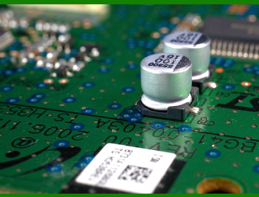
Capacitors and Transistors: These components are often integrated into the microchip to manage the power and signal flow within the RFID system. Capacitors store charge, while transistors act as switches for controlling the electrical signals. |
|
3. Working Principle of RFID Tags |
RFID tags operate based on the principle of electromagnetic induction and reflection. When an RFID reader sends out a signal in the form of electromagnetic waves, the RFID tag's antenna receives these waves and converts them into electrical energy. For passive tags, this energy is used to power the microchip, which then sends a response back to the reader. |
Passive RFID Tags: These tags do not have their own power source. Instead, they rely on the electromagnetic energy received from the reader¡¯s signal. This energy powers the chip and enables the transmission of data back to the reader. |
Active RFID Tags: These tags contain an onboard battery that powers the chip continuously, enabling them to send out signals even when not interrogated by the reader. Active tags can transmit signals over greater distances compared to passive tags. |
Semi-Passive RFID Tags: These tags have a battery that powers the chip, but like passive tags, they do not transmit a signal unless they are activated by a reader's signal. |

|
4. RFID Tag Circuit Design |
RFID tag circuit design involves several considerations to ensure proper functioning of the tag within the RFID system. These considerations include the choice of power source, data storage capacity, communication protocol, and the antenna design. |
Power Source Design: For passive RFID tags, the design of the power harvesting circuit is crucial. The circuit must efficiently capture energy from the RFID reader¡¯s signal and convert it into usable DC power for the microchip. This often involves a rectifier circuit, which converts the alternating current (AC) signal from the reader into direct current (DC). |
Data Processing and Memory: The microchip contains a processing unit that decodes the incoming signal, processes the information, and stores the data in memory. Depending on the RFID tag¡¯s design, the chip might have multiple memory banks, such as read-only memory (ROM) for storing the tag¡¯s unique ID, and read/write memory (RW) for dynamic data storage. |
Antenna Circuit: The antenna is designed to match the frequency of the RFID system (typically low-frequency, high-frequency, or ultra-high frequency). The antenna¡¯s impedance must be matched with the RFID reader¡¯s output impedance to ensure efficient energy transfer. The antenna circuit typically includes a matching network that adjusts the impedance and minimizes signal loss. |
Signal Modulation: To transmit data, RFID tags use various modulation techniques, such as amplitude modulation (AM), frequency modulation (FM), or phase modulation (PM). These techniques allow the RFID tag to encode and transmit information in the form of radio waves. |

|
5. Types of RFID Tag Circuits |
RFID tags can be broadly categorized into several types based on their circuit design and power source. |
5.1 Passive RFID Tag Circuits |
Energy Harvesting Circuit: In passive RFID tags, the energy harvesting circuit is designed to collect energy from the RFID reader's signal and store it in capacitors for later use. This circuit ensures that even with very little power, the microchip can function. |
Rectifier and Voltage Regulator: The rectifier circuit converts the AC signal from the reader into DC voltage, while the voltage regulator ensures the voltage is stable enough to power the microchip. |
5.2 Active RFID Tag Circuits |
Battery-Powered Circuit: Active tags have a built-in battery that continuously powers the tag¡¯s microchip and transmission circuitry. The battery design is crucial for maintaining long operational lifetimes, especially in large-scale deployments. |
Signal Transmission Circuit: In active tags, the microchip is continuously powered, which allows the tag to periodically broadcast its information even without the reader¡¯s intervention. The transmission circuit includes a modulator that encodes the tag's data into the radio signal. |
5.3 Semi-Passive RFID Tag Circuits |
Battery-Assisted Circuit: Semi-passive tags rely on an internal battery to power the chip, but the transmission circuit is still activated by the reader's signal. The design of these circuits allows for a longer operational range than passive tags but at a reduced power consumption compared to fully active tags. |
|
6. Frequency and Bandwidth Considerations |
RFID systems operate at different frequencies, each of which has its own advantages and trade-offs in terms of power consumption, communication range, and data transfer speed. |
Low-Frequency (LF) RFID: Operating in the range of 125¨C134 kHz, LF RFID tags have a shorter communication range but are less affected by interference from metals and liquids. These tags are commonly used in animal tracking, access control, and asset management. |
High-Frequency (HF) RFID: Operating in the 13.56 MHz range, HF tags offer medium-range communication and are commonly used in contactless payment systems, library books, and access control. |
Ultra-High-Frequency (UHF) RFID: Operating between 860 and 960 MHz, UHF tags can communicate over long distances and are commonly used for inventory tracking, logistics, and retail applications. |
Microwave RFID: Operating at even higher frequencies (typically 2.45 GHz), microwave RFID tags offer the longest range and fastest data transfer, but they can be more susceptible to interference from environmental factors. |
The frequency and bandwidth of the RFID tag's communication circuit determine its data transfer rate, power consumption, and operating range. The circuit must be optimized to function within the designated frequency range and handle the modulation techniques required for that frequency. |

|
7. Signal Integrity and Noise Reduction |
RFID tags operate in environments where there may be various sources of electrical noise, such as nearby electronic devices, metals, or liquids. Proper circuit design is essential to ensure reliable communication by minimizing the impact of interference. Some techniques used to improve signal integrity include: |
Filtering Circuits: These circuits help to remove unwanted noise and signal distortion by only allowing the desired frequency to pass through. |
Shielding: Physical shielding can be used around the RFID tag's antenna and circuitry to block external electromagnetic interference (EMI). |
Error Correction Algorithms: Some RFID systems implement error detection and correction algorithms to ensure the accuracy of data transmission, even in the presence of noise. |

|
8. Tag Performance and Durability |
The performance and durability of an RFID tag depend on the design of its circuit, particularly the antenna and microchip. The circuit must be able to handle environmental stressors such as temperature extremes, humidity, and physical wear. To improve durability: |
Encapsulation: The RFID tag¡¯s circuit is often encapsulated in a protective material, such as epoxy resin or plastic, to protect it from mechanical damage, moisture, and chemicals. |
Robust Circuit Design: Advanced circuit designs use components that are specifically chosen for their reliability and durability, such as temperature-resistant capacitors and resistors. |
|
9. Security and Privacy Features in RFID Tags |
RFID tags are also subject to concerns regarding data security and privacy. Since RFID tags communicate wirelessly, it is possible for unauthorized parties to intercept or manipulate the transmitted data. To address these concerns, RFID tags incorporate security features such as: |
Encryption: Data stored on the RFID tag can be encrypted to prevent unauthorized access. |
Authentication Protocols: Some RFID systems include authentication mechanisms to verify the identity of the RFID tag and prevent cloning or counterfeiting. |
Privacy-Preserving Features: Some tags include features such as rolling codes, where the tag¡¯s identifier changes periodically to prevent tracking over long periods. |

|
10. Conclusion |
The RFID tag¡¯s circuit structure is a highly intricate system that involves energy harvesting, data storage, signal modulation, and secure communication. The design of these circuits must be optimized to meet specific requirements such as communication range, power consumption, durability, and security. As RFID technology continues to evolve, new materials, components, and circuit architectures are being developed to improve the efficiency and functionality of RFID tags for a variety of applications, including inventory management, supply chain tracking, access control, and contactless payments. |
This detailed explanation of the circuit structure principles of RFID tags provides an understanding of the underlying mechanisms that drive RFID technology, allowing for more effective design, deployment, and optimization of RFID systems in various industries. |

|
Deep into the Microchip (Integrated Circuit) od RFID tag |
1. Introduction to RFID Microchip (Integrated Circuit) |
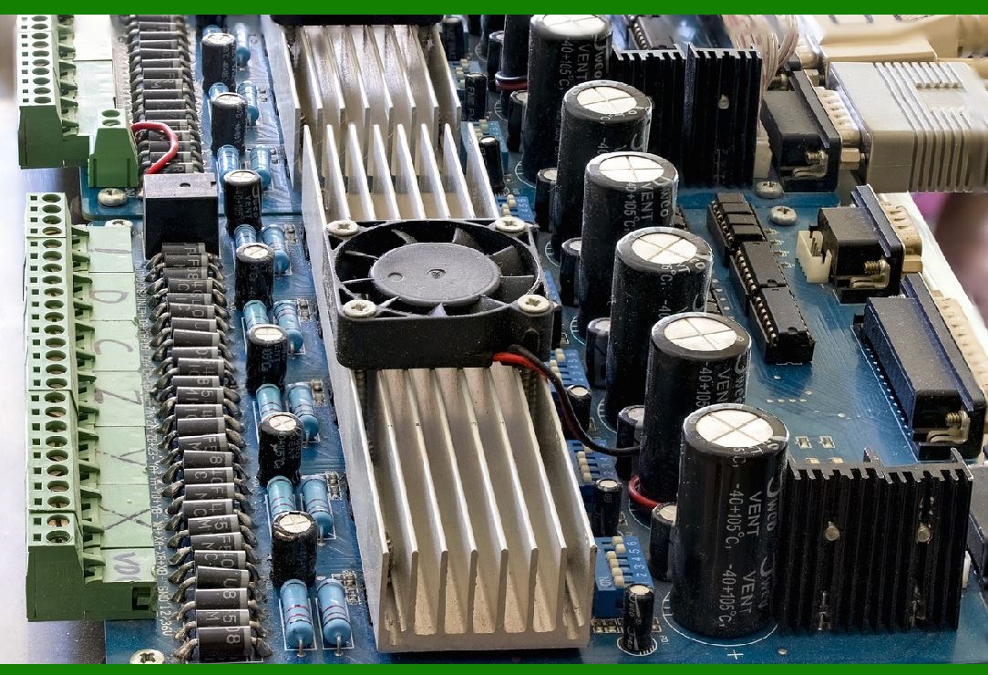
The microchip, or integrated circuit (IC), in an RFID tag is the central component that allows the tag to store data, communicate with readers, and perform specific tasks. The IC is typically made from semiconductor materials such as silicon and is housed within the RFID tag's protective casing. The microchip serves as the ¡°brain¡± of the RFID tag, processing the information, managing the communication protocols, and providing security features. |
The RFID microchip can be broadly categorized based on the type of RFID tag: passive, active, or semi-passive. Each category of RFID tag requires a different approach to microchip design to accommodate its power requirements, data storage capacity, and communication needs. |
|
2. Basic Structure and Functionality of the RFID Microchip |
The microchip in an RFID tag consists of several key functional blocks that perform various tasks necessary for tag operation: |
Memory: The microchip contains different types of memory that store information, such as the unique tag identifier (UID) and other data. Memory can be classified as: |
Read-Only Memory (ROM): Stores the permanent, unique identifier (UID) that is programmed during the manufacturing process. This data is non-erasable. |
Read/Write Memory (RW): This is the portion of the memory where data can be both written and read by the RFID reader. The data in this area can be changed dynamically and is used for temporary storage, such as inventory counts or transaction logs. |
Erasable Programmable Read-Only Memory (EPROM): This memory type is commonly used in tags that require the ability to be rewritten but need to retain data for longer periods. |
Processor/Control Unit: This block is responsible for managing the operation of the chip, controlling data flow, interpreting signals, and interfacing with the memory. The processor handles various tasks, including: |
Signal modulation and demodulation: The processor encodes data to be transmitted to the reader and decodes incoming signals. |
Protocol handling: The processor interprets the communication protocol (such as EPCglobal, ISO 18000, etc.) and ensures compatibility with RFID readers. |
Error correction: The processor may implement error correction algorithms to ensure data integrity during transmission. |
Power Management Circuit: This circuit regulates the power supplied to the microchip, ensuring that it functions within its required voltage range. The power management circuit plays a crucial role, especially in passive RFID tags, where the chip relies on energy harvested from the RFID reader¡¯s signal. |
Communication Circuit: The communication circuit, often paired with the antenna, is responsible for enabling the chip to send and receive signals. It performs tasks such as: |
Modulation/Demodulation: This component encodes the data for transmission (amplitude modulation, frequency modulation, or phase modulation), and decodes incoming signals. |
Signal Transmitter/Receiver: The communication circuit typically interfaces with the tag¡¯s antenna to transmit and receive radio signals. |
Security Module (Optional): Many RFID microchips include a security module to protect data stored on the tag and to secure communication between the tag and the reader. This module often includes: |
Encryption and decryption units: To protect sensitive data, many RFID systems use encryption techniques to encode data before transmission and decrypt it at the receiver end. |
Authentication protocols: To prevent unauthorized access, some tags use mutual authentication protocols to ensure that only authorized readers can access the data. |

|
3. Power Management in the RFID Microchip |
Power management is a critical aspect of RFID tag design. Depending on the type of RFID tag (passive, active, or semi-passive), the microchip¡¯s power requirements differ significantly. |
3.1 Passive RFID Microchips |
In passive RFID systems, the microchip does not have a battery and instead relies on the energy provided by the RFID reader. When the reader sends a radio frequency (RF) signal, the tag's antenna picks up the signal, and the microchip harvests a small portion of this energy. This energy is typically stored temporarily in a capacitor and used to power the microchip for the duration of the communication. Passive RFID microchips rely on an energy harvesting circuit and rectifier circuit to convert the RF energy into a usable DC voltage. |
Rectifier: Converts the AC signal received by the antenna into a DC voltage to power the chip. |
Voltage Regulator: Maintains a constant voltage level for the chip to function correctly. |
Capacitor: Temporarily stores energy, enabling the microchip to perform its operations even when the signal from the reader is weak or intermittent. |
3.2 Active and Semi-Passive RFID Microchips |
Active and semi-passive RFID tags have their own battery to continuously power the microchip. These microchips do not need to rely on energy harvesting from the reader and can transmit signals autonomously. However, power management is still crucial for extending the tag's operational lifetime. |
Power Consumption: Active tags require power for continuous signal transmission, and their microchips are designed to manage the power consumption efficiently, balancing between active and idle states to conserve battery life. |
Battery Monitoring: Some RFID microchips are equipped with sensors to monitor battery life and provide notifications when the battery is running low. |
|
4. Signal Modulation and Communication Protocols |
One of the most critical aspects of the RFID microchip is its ability to communicate with the reader and encode the data it stores. RFID systems typically use modulation techniques to transmit information over the radio waves. The microchip uses a specific protocol to encode and decode signals, ensuring compatibility with the reader. |
4.1 Modulation Types |
The RFID microchip modulates the signal by varying certain parameters of the radio wave, such as amplitude, frequency, or phase. Some common modulation schemes include: |
Amplitude Modulation (AM): The microchip modulates the amplitude (strength) of the signal to encode data. |
Frequency Modulation (FM): In this scheme, the frequency of the signal is varied to encode data. |
Phase Modulation (PM): The phase of the signal is altered by the microchip to represent the encoded data. |
4.2 Communication Protocols |
The communication protocol defines the rules for data exchange between the RFID tag and the reader. RFID protocols include both low-level hardware specifications and higher-level data exchange formats. Some common RFID communication protocols include: |
ISO 14443: Used for proximity cards, such as those used in contactless payment systems and access control. |
EPCglobal (Gen 2): A widely used protocol for item-level tracking in retail, logistics, and supply chain management. |
ISO 18000: A family of standards for different frequencies, including LF, HF, and UHF RFID. |
The microchip handles the protocol processing by ensuring that the data transmitted from the chip is in the correct format and that the data received is properly decoded. |

|
5. Error Detection and Correction |
Given that RFID tags communicate wirelessly, errors may occur due to signal interference, weak signals, or other environmental factors. To ensure the integrity of data transmission, RFID microchips implement various error detection and correction mechanisms. |
5.1 Error Detection |
Error detection involves checking the data received for anomalies or corruption. Common techniques include: |
Parity Checking: A simple method of checking for errors by adding an extra bit to the data, making the total number of 1s either even or odd. |
Checksums: The microchip calculates a checksum value based on the data, which is sent along with the data. The reader recalculates the checksum to verify the data integrity. |
5.2 Error Correction |
Error correction techniques ensure that data can be reconstructed even if part of the signal is lost or corrupted. These techniques typically use forward error correction (FEC) algorithms, such as: |
Hamming Code: A widely used error correction technique where additional bits are added to the data, allowing the reader to correct single-bit errors automatically. |
Reed-Solomon Codes: These codes are used in more complex systems, allowing the reader to recover from multiple errors in the transmitted data. |

|
6. Security Features in RFID Microchips |
With the increasing adoption of RFID technology, ensuring the security and privacy of data transmitted by RFID tags has become paramount. Many RFID microchips are designed with integrated security features to prevent unauthorized access, tampering, or cloning of RFID tags. |
6.1 Encryption |
Data stored on the RFID microchip can be encrypted to prevent unauthorized reading or interception. The encryption is typically based on advanced cryptographic algorithms such as AES (Advanced Encryption Standard) or DES (Data Encryption Standard). This ensures that even if an attacker intercepts the communication, they cannot read or modify the data. |
6.2 Authentication |
Many RFID systems implement mutual authentication, where both the tag and the reader must prove their identities before communication is allowed. This can be achieved using challenge-response protocols in which the reader sends a challenge, and the tag provides a response that proves its identity. |
6.3 Secure Keys |
Some RFID microchips come with built-in secure key storage that ensures the integrity of the data and authentication processes. The keys are securely stored within the chip and are used to encrypt communication between the tag and reader. |

|
7. Conclusion |
The microchip (integrated circuit) within an RFID tag is a complex, multi-functional component responsible for the storage, processing, and communication of data. It consists of various elements, including memory, a processor, power management circuits, communication circuits, and security modules, all working together to enable the RFID tag to function efficiently. Advances in microchip technology continue to drive innovations in RFID systems, enhancing their capabilities in terms of range, security, data capacity, and energy efficiency. |

|
Deep into Passive RFID Tags: These tags do not have their own power source. Instead, they rely on the electromagnetic energy received from the reader¡¯s signal. |
1. Introduction to Passive RFID Tags |
Passive RFID tags are one of the most common types of RFID tags, especially in applications such as inventory management, asset tracking, and contactless payment systems. Unlike active RFID tags, which contain their own battery, passive RFID tags do not have a power source of their own. Instead, they rely on the electromagnetic energy transmitted by the RFID reader to power the chip and transmit data back to the reader. |
Because passive RFID tags are energy-efficient and cost-effective, they are widely used in industries ranging from retail to logistics and healthcare. Their ability to function without an internal battery makes them lightweight, small, and durable, which is essential for many applications. |

|
2. Basic Working Principle of Passive RFID Tags |
Passive RFID tags operate using a basic principle of electromagnetic induction, where energy from the reader¡¯s signal is used to power the tag¡¯s microchip. Here¡¯s how the process works: |
2.1 Signal Transmission from RFID Reader |
An RFID reader transmits a radio frequency (RF) signal into the environment. This signal is emitted at a specific frequency, typically within one of the RFID bands: Low Frequency (LF), High Frequency (HF), or Ultra High Frequency (UHF). The RFID reader sends this signal continuously or at regular intervals, depending on the system. |
2.2 Energy Harvesting |
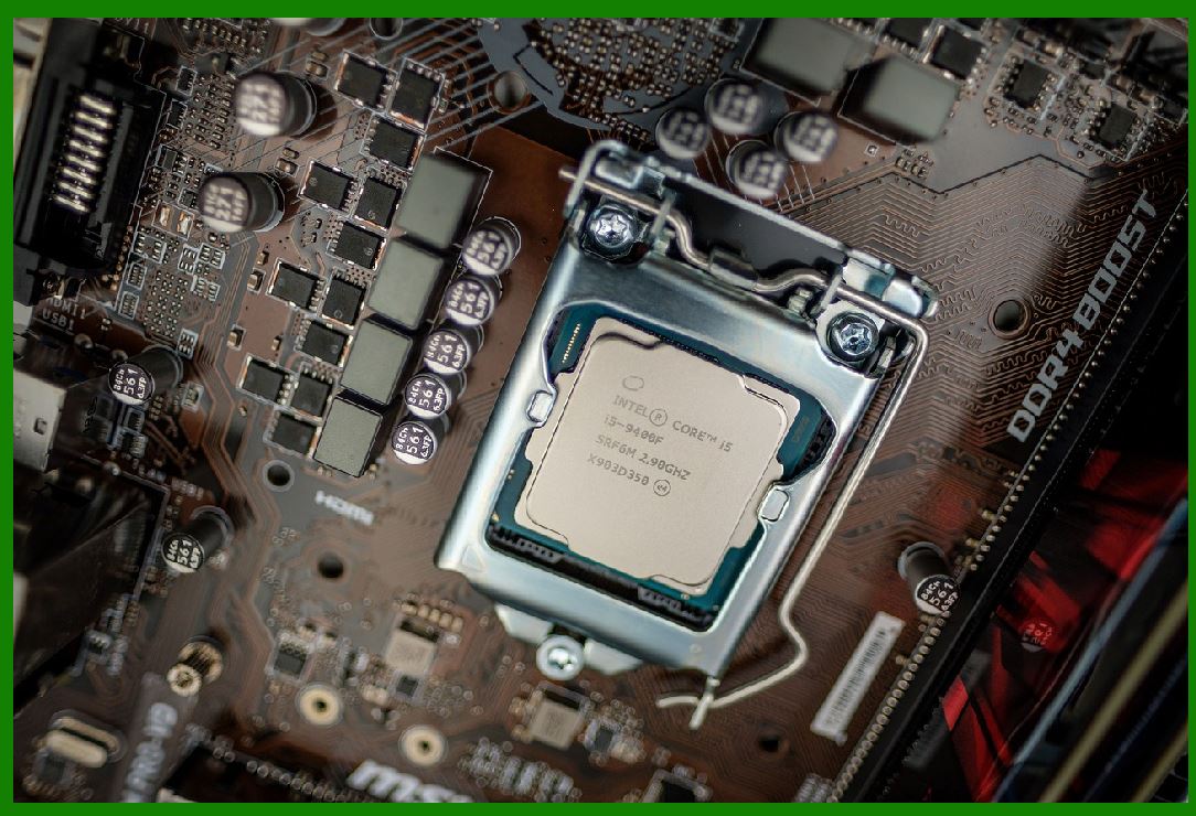
Passive RFID tags are designed with an antenna and an energy harvesting circuit. The tag¡¯s antenna captures the electromagnetic energy from the reader¡¯s signal and converts it into a usable form (direct current or DC power) to power the chip. This process is known as inductive coupling. |
Antenna: The antenna is the key component that enables the tag to receive the radio signal from the reader. The antenna converts the electromagnetic field from the reader into electrical energy. The size and shape of the antenna are critical in determining the range and efficiency of energy transfer. It¡¯s often made of copper or aluminum in the form of a coil or loop. |
Energy Harvesting Circuit: The energy harvesting circuit collects the energy from the radio waves captured by the antenna and converts it into direct current (DC). This is achieved by using a rectifier circuit, which converts the alternating current (AC) signal received from the antenna into a usable DC voltage. |
2.3 Powering the Microchip |
Once the energy has been harvested and converted into DC power, it is used to power the RFID microchip. The microchip then activates, processes the signal, and prepares the data for transmission back to the reader. In passive RFID tags, the microchip only functions when there is enough energy from the reader's signal. |
Rectifier: The rectifier circuit plays an important role by converting the AC signal from the reader into DC power. A diode is typically used in the rectifier to allow current to flow in one direction, and capacitors may be used to smooth out any voltage fluctuations. |
Voltage Regulator: Since the energy harvested from the reader¡¯s signal can vary in strength (depending on factors like distance and reader power), a voltage regulator is often employed to ensure that the microchip receives a stable voltage. This helps protect the chip from under-voltage or over-voltage conditions, allowing it to function reliably. |
2.4 Data Transmission |
Once the microchip is powered and ready, it responds to the reader's signal. Passive RFID tags typically use backscatter communication to send data back to the reader. This process is referred to as 'backscattering' because the tag reflects the reader¡¯s signal back, modulating it to encode data. |
Modulation: The microchip modulates the backscattered signal to encode the information, such as the tag¡¯s unique identifier (UID) or other data stored in the memory. The data encoding process can use various modulation schemes, such as amplitude modulation (AM), frequency modulation (FM), or phase modulation (PM). |
Antenna Reflection: The modulated signal is transmitted back to the reader by the antenna. The RFID reader detects the reflected signal and decodes the information, interpreting the data transmitted by the passive RFID tag. |
|
3. Key Components of Passive RFID Tags |
The passive RFID tag circuit comprises several key components that work together to enable communication with the reader. Each of these components plays a vital role in ensuring efficient power transfer, data storage, and reliable signal transmission. |
3.1 Antenna |
The antenna is the first point of interaction between the RFID tag and the reader¡¯s signal. The antenna captures the electromagnetic energy from the reader's RF signal and converts it into electrical energy, powering the microchip. |
Antenna Design: The antenna design is critical for the range and performance of passive RFID tags. It determines how efficiently the tag can capture energy from the reader's signal and how effectively the tag can transmit data back. The antenna¡¯s geometry and material properties influence the efficiency of energy transfer. For example, UHF tags typically use a longer antenna to capture energy from longer-range signals. |
3.2 Rectifier Circuit |
The rectifier circuit converts the alternating current (AC) signal from the RFID reader into a usable direct current (DC). |
Bridge Rectifier: Many passive RFID tags use a bridge rectifier circuit to ensure that the voltage is always converted to a steady DC. A bridge rectifier consists of four diodes arranged in a bridge configuration to convert both halves of the AC waveform into positive voltage. |
Capacitors: Capacitors are used to store energy briefly and smooth out any fluctuations in the DC voltage, ensuring that the power provided to the microchip remains stable. |
3.3 Microchip (IC) |
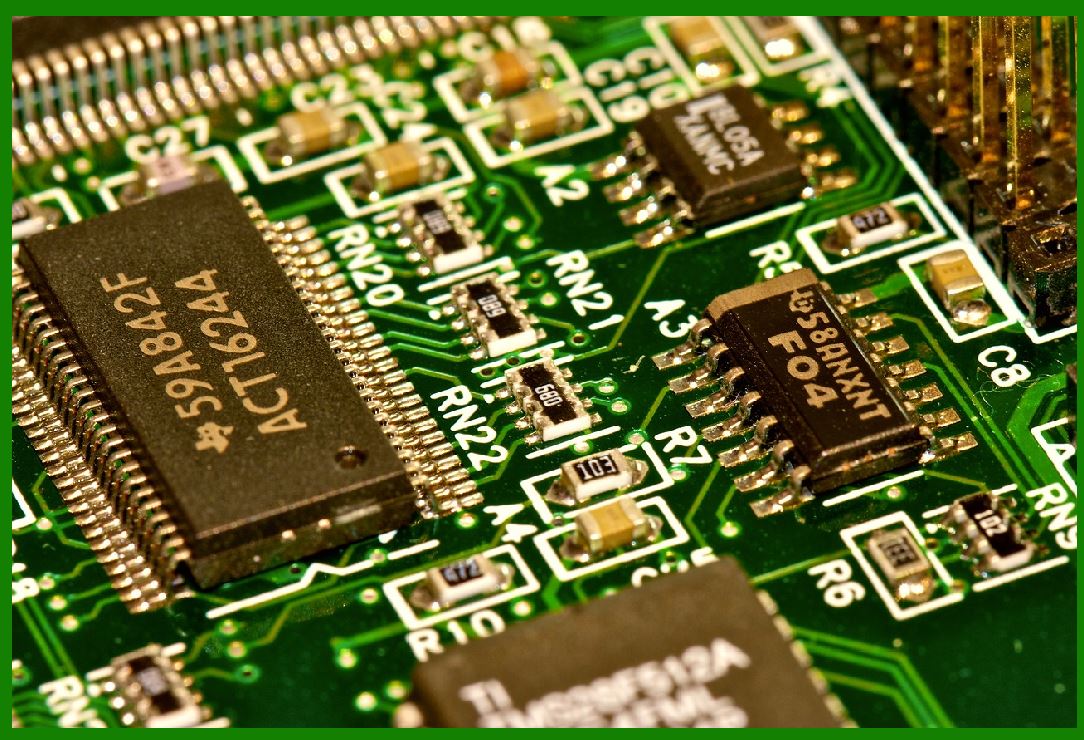
The microchip, also known as the integrated circuit (IC), is the 'brain' of the RFID tag. It stores the tag¡¯s unique identifier (UID) and may also include additional memory for storing user data. |
Memory: The memory in passive RFID tags is typically divided into read-only memory (ROM) for the UID and read/write memory (RW) for data that can be modified during the tag's use. |
Protocol Handler: The microchip handles communication protocols (e.g., ISO 14443, EPC Gen 2) and encodes or decodes data based on the reader¡¯s query. |
Control Logic: The microchip controls the interaction between the antenna and the reader, ensuring that data is transmitted efficiently and that the tag operates within the parameters set by the reader. |
3.4 Voltage Regulator |
Passive RFID tags rely on the harvested energy to power the microchip. The voltage regulator ensures that the voltage delivered to the chip remains consistent, even if the energy harvested fluctuates. |
Low Dropout Regulator (LDO): In many passive RFID tags, an LDO voltage regulator is used because it can maintain a stable output voltage even when the input voltage (harvested from the reader) is only slightly higher than the required voltage for the microchip. |
|
4. Communication and Modulation |
Passive RFID tags communicate with the reader using a backscatter technique, where the tag modulates the strength of the signal it reflects back to the reader. |
Backscatter Modulation: The passive RFID tag does not generate its own RF signal. Instead, it modulates the strength (amplitude), frequency, or phase of the incoming signal and reflects it back toward the reader. This allows the tag to send its stored data to the reader. |
Data Encoding: The data encoded in the modulated signal may represent the unique identifier of the tag or other information stored in the tag¡¯s memory. The modulation scheme may vary depending on the tag's communication protocol (e.g., EPC Gen 2 uses frequency shift keying). |

|
5. Range and Efficiency |
The operational range of passive RFID tags is typically shorter than that of active RFID tags because they rely entirely on the energy provided by the reader. However, the range of a passive RFID tag is influenced by several factors: |
5.1 Reader Power Output |
The stronger the reader¡¯s signal, the further the passive RFID tag can communicate. However, there is a trade-off between signal strength and interference, especially in environments with high levels of radio frequency interference (RFI). |
5.2 Antenna Design |
The design and placement of the antenna in the RFID tag are crucial factors in determining its communication range. The larger the antenna, the more energy it can capture, thus increasing the range and performance. |
5.3 Frequency Band |
The frequency at which the passive RFID tag operates also plays a critical role in range. For instance, UHF RFID tags typically offer longer ranges (up to 100 meters in ideal conditions) than LF and HF RFID tags, which have shorter ranges (up to 1¨C2 meters). |

|
6. Applications of Passive RFID Tags |
Passive RFID tags are widely used in a variety of industries due to their low cost, small size, and ability to function without an internal battery. Key applications include: |
Inventory and Asset Tracking: Passive RFID tags are commonly used to track products, assets, and inventory in real-time in industries such as retail, logistics, and healthcare. |
Supply Chain Management: These tags enable seamless tracking and traceability of goods as they move through the supply chain, improving visibility and efficiency. |
Access Control: Passive RFID tags are used in access control systems, such as ID badges and smart cards, to provide secure entry to buildings or restricted areas. |
Libraries and Document Management: Passive RFID tags are used to track books, files, and other assets in libraries and offices. |
Retail and Point of Sale: Passive RFID tags help retailers manage inventory, reduce theft, and streamline checkout processes. |

|
7. Conclusion |
Passive RFID tags offer a powerful and efficient solution for wireless data transmission, relying on energy harvested from a reader¡¯s RF signal to operate. The combination of small size, low cost, and minimal power requirements makes passive RFID tags ideal for a wide range of applications, from inventory tracking to security and beyond. With further improvements in antenna design, energy harvesting techniques, and communication protocols, the effectiveness and range of passive RFID tags will continue to grow, enabling more innovative uses in various industries. |

|
Deep into Energy Harvesting Circuit |
1. Introduction to Energy Harvesting in Passive RFID Tags |
In passive RFID tags, the energy harvesting circuit is one of the most critical components. This circuit enables the tag to collect electromagnetic energy from the RFID reader¡¯s transmitted radio frequency (RF) signal and convert it into usable electrical power. Since passive RFID tags do not have a built-in battery, they rely entirely on this harvested energy to power the microchip, allowing it to communicate with the reader. |
The energy harvesting circuit has to work efficiently in very low-power conditions because passive RFID tags typically operate in environments where the energy received from the reader¡¯s signal is minimal. Despite this challenge, the energy harvesting circuit must ensure that enough power is captured, stored, and managed to allow the tag to operate effectively, even when the received signal is weak or intermittent. |

|
2. Working Principle of Energy Harvesting Circuit |
The energy harvesting circuit in a passive RFID tag works by utilizing the electromagnetic waves emitted by the RFID reader. These waves are captured by the tag¡¯s antenna, and the energy is transferred to the rectifier circuit, where it is converted into direct current (DC) power. This energy is then stored in capacitors and used to power the tag¡¯s microchip and other components. |
The energy harvesting process can be broken down into several key stages: |
2.1 Signal Reception |
Antenna: The RFID tag¡¯s antenna is designed to capture the electromagnetic signal transmitted by the RFID reader. It works by converting the incoming RF signal into electrical energy. The antenna is typically made of a conductor (such as copper or aluminum) and is designed to resonate at a specific frequency, matching the operating frequency of the RFID system (e.g., LF, HF, or UHF). |
Power Capture: The antenna captures a portion of the radio waves and converts them into an AC electrical signal. This AC signal is then passed to the rectifier circuit, where it will be converted into DC power for use by the tag¡¯s chip. |
2.2 Energy Conversion |
Rectifier Circuit: The rectifier is a crucial component in the energy harvesting circuit. It converts the AC signal received from the antenna into DC power, which is required to operate the microchip and other components in the RFID tag. The rectifier typically consists of diodes arranged in a bridge configuration to allow current to flow in one direction, ensuring that only DC power reaches the tag¡¯s circuitry. |
Bridge Rectifier: Most passive RFID tags use a full-wave bridge rectifier circuit. This type of rectifier uses four diodes arranged in a specific configuration to convert both halves of the AC waveform into positive DC. A full-wave bridge rectifier is more efficient than a half-wave rectifier because it utilizes both the positive and negative portions of the AC signal. |
Capacitors: The rectifier circuit generates DC power, but the voltage can fluctuate depending on the strength of the incoming signal. Capacitors are used to smooth the DC voltage by storing the electrical charge during the peaks of the AC signal and releasing it during the troughs. Capacitors essentially act as energy reservoirs, helping to maintain a stable voltage level for the tag¡¯s microchip to operate. |
Capacitor Types: Typically, electrolytic capacitors or ceramic capacitors are used for this energy storage. These capacitors have a high capacitance, allowing them to store more energy. |
2.3 Voltage Regulation |
Once the AC signal is converted into DC power and stored in capacitors, it is important to regulate the voltage to ensure that the microchip receives a stable and constant supply of power. Variations in the harvested energy due to distance from the reader, interference, or other factors can result in unstable voltage levels. A voltage regulator helps manage these fluctuations. |
Low Dropout Regulator (LDO): In passive RFID tags, Low Dropout Regulators (LDOs) are often used to ensure that the voltage provided to the microchip remains stable. LDOs are efficient voltage regulators that can operate with minimal input-to-output voltage difference. This is essential in RFID tags, where the voltage received from the energy harvesting circuit can sometimes be only slightly higher than the required voltage for the microchip. |
Voltage Clamping: To prevent overvoltage from damaging the microchip, voltage-clamping circuits, such as Zener diodes, may be used to limit the maximum voltage that can reach the microchip. |
2.4 Energy Storage |
After the energy has been harvested and converted to DC, it is temporarily stored in a capacitor or a supercapacitor. Capacitors serve as short-term energy reservoirs, providing power to the tag's microchip when the harvested energy is insufficient or intermittent. The use of capacitors also helps to stabilize the voltage supplied to the chip, ensuring that it operates reliably during the communication process with the reader. |
Supercapacitors: In some advanced RFID designs, supercapacitors are used instead of regular capacitors due to their higher energy density and longer life cycles. Supercapacitors can store significantly more energy than regular capacitors, providing the microchip with a more stable power source during weak signal conditions. |
2.5 Power Distribution |
Once the energy is harvested, converted, and stored, it is then distributed to the microchip and any other components in the RFID tag. The power distribution network ensures that the microchip receives the proper amount of energy required for its operation, including the ability to transmit and receive data. |
Power Switching: Passive RFID tags often use power switches that help manage the flow of energy between the capacitor and the microchip, ensuring that power is available when needed. |
Power Efficiency: A well-designed energy harvesting circuit ensures that the power conversion and storage processes are as efficient as possible, minimizing power loss and maximizing the time the tag can operate. |
|
3. Factors Affecting the Energy Harvesting Circuit Performance |
The efficiency and reliability of the energy harvesting circuit in passive RFID tags can be affected by several factors. These factors must be carefully considered during the design process to ensure optimal performance: |
3.1 Reader Signal Strength |
The strength of the RFID reader¡¯s signal is a critical factor in how much energy the tag can harvest. The closer the tag is to the reader, the more energy it can capture. The relationship between the reader¡¯s output power and the harvested energy is non-linear, so even small changes in the reader's distance or power level can have a significant impact on the energy available to the tag. |
Signal Attenuation: In real-world environments, obstacles such as walls, metals, and liquids can cause the RFID signal to weaken as it propagates. This can reduce the amount of energy harvested by the tag. |
3.2 Tag Antenna Design |
The efficiency of the energy harvesting process is strongly influenced by the design of the RFID tag¡¯s antenna. The antenna must be designed to match the frequency of the RFID reader¡¯s signal and to maximize the amount of energy it can capture. The size, shape, and material of the antenna all affect its ability to harvest energy. |
Antenna Impedance Matching: The impedance of the tag¡¯s antenna must match the impedance of the reader to minimize signal reflection and maximize energy transfer efficiency. |
3.3 Distance Between the Tag and Reader |
The range of communication between the tag and the reader is directly related to the amount of energy harvested. Tags that operate at longer ranges need more power, which means the energy harvesting circuit must be optimized to capture energy from a weaker signal over greater distances. |
Fresnel Zone: The effective communication range also depends on the tag¡¯s orientation relative to the reader. For maximum energy harvesting efficiency, the tag should be positioned in the optimal path of the reader¡¯s signal. |
3.4 Environmental Conditions |
The environment in which the RFID system operates can have a significant impact on the performance of the energy harvesting circuit. Factors like temperature, humidity, and the presence of electromagnetic interference (EMI) can affect the efficiency of the circuit and the stability of the power supply to the microchip. |
Temperature Sensitivity: Capacitors, diodes, and voltage regulators used in energy harvesting circuits have temperature-dependent performance characteristics. Extreme temperatures can reduce their efficiency, requiring additional design considerations to ensure stable operation in a wide range of conditions. |
3.5 Efficiency of Power Conversion and Storage |
The overall efficiency of the energy harvesting circuit depends on how effectively the harvested energy is converted, regulated, and stored. Losses can occur at each stage of energy conversion (rectification, regulation, storage), so minimizing these losses is critical to ensuring the RFID tag¡¯s performance. |
Conversion Losses: A portion of the energy is lost during the rectification process (due to the inherent properties of diodes) and during voltage regulation. Optimizing the design of the rectifier and voltage regulator can reduce these losses. |
|
4. Applications of Energy Harvesting in Passive RFID Tags |
The ability to harvest energy from the RFID reader¡¯s signal allows passive RFID tags to be used in a wide variety of applications. These applications benefit from the tag¡¯s small size, long operational life, and low cost. |
4.1 Inventory Management and Asset Tracking |
Passive RFID tags are widely used in retail, logistics, and supply chain management for tracking inventory and assets in real-time. By harvesting energy from the RFID reader¡¯s signal, tags can be attached to items and easily read during routine inventory scans, enabling automated tracking and management. |
4.2 Healthcare and Medical Devices |
In healthcare, passive RFID tags can be used for patient tracking, equipment management, and drug authentication. By using energy harvesting circuits, these tags can operate over long periods without requiring batteries, making them ideal for use in hospitals and medical environments. |
4.3 Access Control |
Passive RFID tags are commonly used in contactless access control systems. The energy harvesting circuit allows the tags to function without a battery, making them a cost-effective solution for security applications. |
4.4 Supply Chain and Logistics |
Passive RFID tags play a crucial role in logistics and supply chain management, where they can be used to track shipments, monitor storage conditions, and manage warehouse inventories. Their ability to harvest energy from the reader signal allows for low-maintenance, long-life operation. |
|
5. Conclusion |
The energy harvesting circuit in passive RFID tags is a critical component that enables these tags to function without a battery. By capturing and converting energy from the RFID reader¡¯s signal, storing it in capacitors, and regulating the power supply, the energy harvesting circuit ensures that the tag¡¯s microchip remains powered and capable of communication. As RFID technology continues to evolve, improvements in energy harvesting efficiency and energy storage capabilities will further enhance the performance and range of passive RFID tags. |
|
Deep into Security and Privacy Features in RFID Tags |
1. Introduction to Security and Privacy Features in RFID Tags |
The widespread use of RFID technology in applications such as inventory management, asset tracking, payment systems, and access control has raised significant concerns regarding the security and privacy of the data transmitted by RFID tags. Unlike traditional barcodes, RFID tags transmit data wirelessly and can be read from a distance, making them more vulnerable to unauthorized access, eavesdropping, and spoofing. |
As a result, security and privacy features in RFID tags have become critical considerations during the design and deployment of RFID systems. These features aim to protect the data stored on the tags, ensure secure communication between the tag and the reader, and safeguard user privacy. |
This deep dive into the security and privacy features in RFID tags will explore various strategies and technologies used to enhance security, prevent unauthorized access, and protect sensitive data from being intercepted or misused. |
|
2. Common Security and Privacy Threats in RFID Systems |
Before delving into the specific security features, it is important to understand the types of threats RFID systems face: |
2.1 Eavesdropping |
Eavesdropping refers to the unauthorized interception of data transmitted between the RFID tag and reader. Since the data in traditional RFID systems is typically transmitted unencrypted, attackers can listen to the RF signals and extract sensitive information, such as the tag's unique identifier (UID) or personal data associated with the tag. |
2.2 Cloning |
An attacker may duplicate an RFID tag by copying its data, allowing the creation of a counterfeit tag with the same UID. This cloned tag can then be used to gain unauthorized access or perform malicious actions, like stealing items or circumventing security controls. |
2.3 Spoofing |
Spoofing occurs when an attacker sends fake RFID signals to a reader, pretending to be a legitimate RFID tag. This can lead to unauthorized access, false identification, or incorrect data being provided to the reader or the system. |
2.4 Data Manipulation |
Data manipulation involves tampering with the data stored on an RFID tag or modifying the communication between the tag and the reader. This could result in incorrect inventory records, fraudulent transactions, or unauthorized changes in access permissions. |
2.5 Tracking and Profiling |
Since RFID tags can be read without direct line-of-sight and from a distance, they can be used to track the movements of individuals or objects over time. This raises significant privacy concerns, especially if sensitive or personal information is associated with the RFID tag. |
|
3. Security Features in RFID Tags |
RFID tag security can be achieved through a combination of encryption, authentication, anti-cloning mechanisms, access control, and other protective measures. Below are the key security features commonly used in RFID tags: |
3.1 Encryption |
Encryption is one of the most effective ways to protect data stored on RFID tags and transmitted between tags and readers. Encryption ensures that even if an attacker intercepts the RFID signal, the data remains unreadable without the appropriate decryption key. |
Symmetric Encryption: This is the most common form of encryption used in RFID systems. The same key is used for both encryption and decryption of the data. A well-known symmetric encryption algorithm used in RFID systems is Advanced Encryption Standard (AES). |
Asymmetric Encryption: In asymmetric encryption, two different keys are used: a public key for encryption and a private key for decryption. While asymmetric encryption is computationally more complex, it offers additional security benefits, such as enabling secure key exchange. |
Session Key Generation: To further enhance security, RFID systems may employ session key generation, where a unique encryption key is generated for each communication session between the tag and the reader. This ensures that even if an attacker intercepts one session, they cannot decrypt future communications. |
|
3.2 Mutual Authentication |
Mutual authentication ensures that both the RFID tag and the reader are authorized to communicate with each other. This two-way authentication process prevents unauthorized readers from accessing sensitive data on the tag and ensures that the tag only responds to authorized readers. |
Challenge-Response Protocol: A common method for mutual authentication in RFID systems is the challenge-response protocol. In this protocol, the reader sends a challenge (a random number or message) to the tag, which then generates a response based on its secret key. The reader verifies the response to ensure that the tag is legitimate. Similarly, the tag may verify the identity of the reader before responding. |
Public Key Infrastructure (PKI): Some RFID systems use PKI-based authentication, where tags and readers have public and private keys for mutual verification. This can help prevent man-in-the-middle attacks and other unauthorized access attempts. |
|
3.3 Access Control and Memory Protection |
RFID tags typically contain several types of memory, such as read-only memory (ROM) for the tag¡¯s unique identifier (UID) and read/write memory (RW) for dynamic data storage. Implementing access control mechanisms ensures that only authorized users or systems can modify or read certain portions of the tag¡¯s memory. |
Password Protection: One way to control access to specific data on an RFID tag is through password protection. A password or PIN is required to access certain memory areas or modify specific fields. This can prevent unauthorized modification of sensitive data. |
Locking and Unlocking Memory Sections: Some RFID tags allow for memory locking, where specific areas of memory can be locked to prevent modification or reading once the data is written. This can be useful for ensuring the integrity of critical information such as UID or authentication keys. |
|
3.4 Anti-Cloning Mechanisms |
One of the most important security features of RFID tags is anti-cloning, which ensures that no one can duplicate the tag's data and create counterfeit copies. Anti-cloning mechanisms are crucial for preventing fraud and unauthorized access. |
Unique Tag Identifiers (UID): Most RFID tags have a unique identifier (UID) that is hardwired into the tag¡¯s memory during manufacturing. However, relying solely on the UID can be problematic for anti-cloning, as it is relatively easy to copy. |
Dynamic Identification: To prevent cloning based on the UID, some RFID systems use dynamic identifiers, which change with each transaction or communication session. This makes it difficult for attackers to clone a tag, as the identifier is constantly evolving. |
Cryptographic Techniques: Some RFID systems employ cryptographic techniques to ensure that the tag¡¯s data cannot be copied. For instance, a hash function may be used to generate a unique identifier based on the tag's data and a secret key. If the attacker tries to clone the tag, the cloned tag will not generate the same hash, making it detectable. |
|
3.5 Secure Data Storage |
Sensitive data stored on RFID tags must be protected to prevent unauthorized access. Data security features include encryption, access control, and storage in tamper-resistant areas of memory. |
Cryptographic Memory: Some RFID tags use cryptographic memory, where encryption keys are stored securely within the tag itself. This ensures that even if an attacker physically captures the tag, they cannot extract or modify the stored data without the appropriate key. |
Tamper Detection: Some RFID tags include tamper detection features, such as sensors that detect when the tag is physically altered. If the tag is tampered with, it can trigger a response (e.g., erasing stored data or disabling the tag), preventing unauthorized access to sensitive information. |
|
3.6 Privacy Protection Features |
One of the major concerns with RFID technology is the potential for tracking and profiling individuals or objects without consent. Privacy protection mechanisms are designed to minimize the risks of unauthorized tracking. |
Killing/Disabling Tags: Many RFID systems allow tags to be permanently disabled once their use is complete. This feature, known as tag killing, ensures that the tag cannot be read or tracked once it is no longer needed. This is especially useful for tags used in smart cards, passports, and library systems. |
Pseudonyms and Rolling Codes: To prevent RFID tags from being used for long-term tracking, some systems employ pseudonyms or rolling codes. Instead of using a static identifier, the RFID tag generates a new, temporary identifier (or pseudonym) for each session or transaction. This helps protect the user¡¯s privacy by making it difficult to associate a specific tag with an individual over time. |
Location-Based Privacy: Privacy protection also includes features that prevent location-based tracking by limiting the read range of RFID tags. This can be done by using low-power RFID systems that require closer proximity to the reader to be activated or by employing directional antennas that limit the scanning range to a specific area. |
|
3.7 Secure Communication Protocols |
In addition to securing the data stored on the tag, securing the communication between the RFID tag and reader is also essential. Secure communication protocols ensure that unauthorized devices cannot interfere with or intercept the data exchange. |
SSL/TLS Encryption: In systems where RFID communication occurs over a network (e.g., RFID-enabled mobile payments), Secure Sockets Layer (SSL) or Transport Layer Security (TLS) protocols can be used to encrypt the entire communication channel. This prevents eavesdropping and tampering with the data being transmitted between the reader and the backend systems. |
ISO/IEC 18000-3: This is a widely adopted protocol standard for HF (High Frequency) RFID systems that includes security features such as authentication and encryption. It provides built-in support for data protection, ensuring that only authorized readers can access the information. |
 cs@easiersoft.com