1. Introduction to RFID and Barcode Joint Reading |
1.1 |
In the modern world of logistics, retail, manufacturing, and supply chain management, automatic identification has become a core technology for achieving efficiency and precision. The two most widely used automatic identification technologies are RFID (Radio Frequency Identification) and barcodes. Each technology has its unique strengths and limitations. RFID offers contactless reading and batch identification, while barcodes are cost-effective, reliable, and widely standardized. |
1.2 |
In many industrial and commercial environments, it is no longer sufficient to rely on just one of these technologies. As goods move quickly through conveyor systems, production lines, or warehouse gates, environmental factors, line speeds, and packaging materials can influence which technology performs best at any given moment. Therefore, an intelligent system capable of jointly reading RFID and barcode labels and dynamically switching between them has become a critical innovation in smart logistics and automation systems. |
1.3 |
The RFID-barcode hybrid reading system integrates two identification subsystems ¡ª one based on electromagnetic radio frequency signals, and the other on optical image processing. By continuously monitoring object motion, system conditions, and environmental feedback, the system can predict the motion state of objects and decide in real-time whether RFID or barcode scanning will yield a more accurate, faster, or more reliable result. This combination achieves both robustness and efficiency, ensuring that identification is successful even when one technology fails due to environmental limitations. |
1.4 |
The core idea is not simply to read both RFID and barcode simultaneously but to create a smart adaptive mechanism that dynamically switches or combines these modes. Such systems can detect whether an object is stationary, moving, accelerating, or rotating, and whether line-of-sight optical visibility is available. Based on these parameters, the system intelligently selects the best method for identification at that moment. |

|
2. Basic Principles of RFID and Barcode Technologies |
2.1 |
Before exploring the combined operation, it is important to understand how each technology works individually. RFID and barcodes serve the same purpose¡ªidentifying items¡ªbut they operate on completely different physical principles. |
2.2 |
RFID (Radio Frequency Identification) works through electromagnetic communication. It consists of two main parts: a reader and an RFID tag. The reader emits radio waves at a specific frequency to power up passive tags or communicate with active ones. Each tag contains a small chip and an antenna that stores a unique identification number and other data. When it receives the reader¡¯s radio signal, it responds by sending back its data through a modulated signal, allowing the reader to capture it. |
2.3 |
Barcodes, on the other hand, rely on optical pattern recognition. A barcode consists of a series of printed lines, dots, or shapes that represent data in a machine-readable form. The barcode scanner (whether laser-based or image-based) illuminates the code and captures reflected light, which is converted into digital data. There are many barcode formats¡ª1D linear codes like Code 128 or UPC, and 2D matrix codes like QR Code or Data Matrix. |
2.4 |
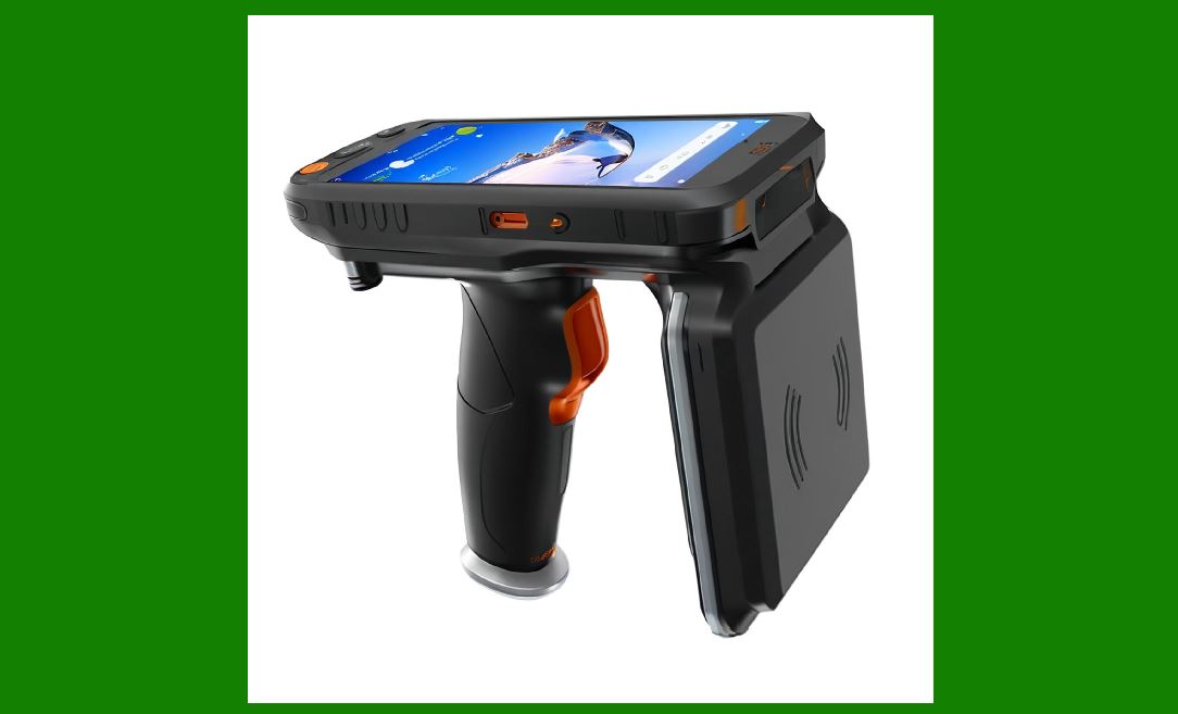
While RFID allows non-line-of-sight and bulk reading, barcodes require optical visibility but offer high precision and low cost. Combining these two allows a system to overcome the weaknesses of each: RFID can be used when visibility is poor or when objects move fast, while barcode reading can be used for visual verification, redundancy, and error correction. |
|
3. The Motivation for Joint Reading Systems |
3.1 |
Traditional RFID or barcode-only systems often face challenges under real-world conditions. For instance, metallic packaging can interfere with RFID signals, and dirty, crumpled, or reflective surfaces can cause barcode scanning errors. In warehouses and production lines, objects often move at varying speeds, making it difficult to guarantee successful scanning every time. |
3.2 |
A hybrid system provides flexibility. It can rely on RFID when the barcode is not visible, such as when items are stacked or packed in boxes. Conversely, when the RFID tag signal is blocked or multiple tags respond simultaneously (causing data collision), the system can fall back to barcode scanning for accuracy. |
3.3 |
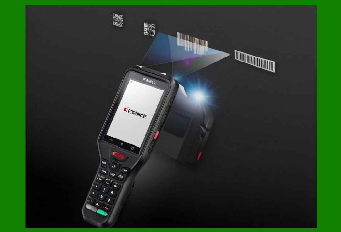
The true innovation lies in dynamic prediction and intelligent switching ¡ª the ability of the system to analyze motion data, predict object trajectories, and select the most appropriate identification method in real time. This dynamic decision-making is achieved through a combination of motion sensors, environmental monitoring, and intelligent software algorithms. |
3.4 |
Such hybrid systems are becoming central to Industry 4.0, smart logistics, warehouse automation, and IoT-based manufacturing. They not only improve identification rates but also reduce the need for manual intervention, lowering costs while increasing reliability. |
|
4. Structure of a Joint RFID and Barcode Reading System |
4.1 |
A joint reading system typically consists of five main components: |
RFID subsystem |
Barcode subsystem |
Motion sensing subsystem |
Environmental and control unit |
Intelligent decision engine (software logic layer) |
4.2 |
The RFID subsystem includes RFID antennas, readers, and control circuits that handle tag interrogation, anti-collision algorithms, and signal decoding. It continuously monitors radio field responses to detect tag presence and distance estimation based on signal strength. |
4.3 |
The barcode subsystem includes one or more camera-based or laser-based scanners capable of recognizing multiple types of barcodes. Modern vision-based readers can even identify codes from different orientations and distances, capturing images for verification or archiving. |
4.4 |
The motion sensing subsystem plays a key role. It may include infrared sensors, ultrasonic rangefinders, laser distance sensors, optical encoders, or machine vision algorithms that estimate an object¡¯s velocity, acceleration, direction, and rotational state. These sensors enable dynamic motion prediction. |
4.5 |
The environmental and control unit gathers contextual information such as lighting, temperature, radio interference, or dust presence. These environmental parameters can significantly affect which reading mode will be more effective. |
4.6 |
Finally, the intelligent decision engine serves as the ¡°brain¡± of the system. It processes input from the other subsystems, compares predicted motion states, evaluates environmental conditions, and dynamically decides: |
When to use RFID only |
When to use barcode scanning only |
When to use both simultaneously |
When to delay or repeat scanning to ensure accuracy |

|
5. The Concept of Dynamic Motion Prediction |
5.1 |
At the heart of intelligent switching is motion prediction. Objects in motion, such as boxes on a conveyor, forklifts, or items being loaded, do not always move at constant speeds. They may accelerate, decelerate, or stop unexpectedly. A smart reading system must anticipate these changes before they occur. |
5.2 |
To achieve this, the system gathers data from motion sensors, such as speed detectors or video frames, and continuously updates an internal model of the object¡¯s trajectory. By analyzing patterns of velocity, displacement, and orientation, it can forecast where the object will be and how fast it will move in the next moments. |
5.3 |
For example, if the system predicts that a package will pass rapidly through a gate in 0.3 seconds, it may activate the RFID subsystem earlier because RFID can handle fast motion. Conversely, if the motion slows down or stops, the system can prioritize barcode scanning to visually confirm identity. |
5.4 |
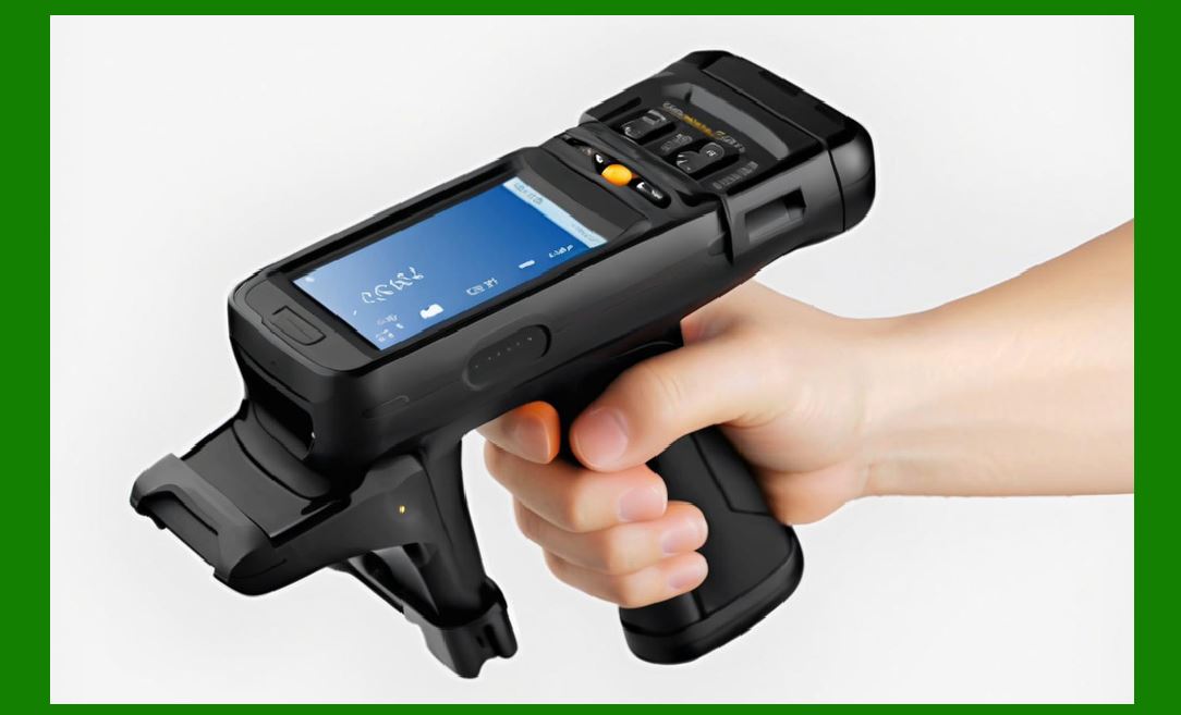
Motion prediction also helps avoid misreads and timing errors. In traditional systems, a scanner might attempt to read a barcode while the item is moving too fast or while the RFID tag is temporarily shielded. Predictive control allows the reader to synchronize its operation precisely with the expected optimal moment. |
|
6. Intelligent Switching Mechanism |
6.1 |
The intelligent switching process is essentially a decision-making loop. It runs continuously, analyzing sensor inputs, motion data, and environmental feedback to select the most appropriate reading mode. |
6.2 |
At every cycle, the system performs three main actions: |
Observation: Collect data from sensors, RFID responses, and barcode visibility analysis. |
Prediction: Estimate the short-term future state of the object (position, speed, orientation, visibility, and radio field strength). |
Decision: Select the most efficient mode (RFID, barcode, or both). |
6.3 |
For instance, when an object is first detected entering a scanning zone, the system measures its initial speed and distance. If the barcode is visible and illumination is stable, it might choose optical scanning. But if the object moves too fast or light reflections are poor, it may instantly switch to RFID mode. |
6.4 |
In some designs, both readers operate in standby mode simultaneously. The decision engine triggers one as primary and uses the other as secondary for redundancy. If the primary fails to confirm identification within a predefined time, the secondary immediately activates. |
6.5 |
This process enables real-time adaptability. The system continuously refines its prediction and decision parameters as it collects new data, allowing it to handle varying motion patterns without human supervision. |

|
7. Example Scenario: Conveyor Belt Sorting |
7.1 |
To understand the joint reading principle in practice, consider a conveyor belt in a logistics warehouse. Each package has both an RFID tag and a barcode label. Packages move along the belt at speeds that can vary from 0.5 to 2 meters per second. |
7.2 |
As a package approaches the reading zone, infrared or laser sensors detect its presence and measure its speed. The control system predicts how long the package will remain in range of the readers. |
7.3 |
If the system predicts that the package will move through too quickly for reliable barcode scanning, it prioritizes RFID. The RFID antenna activates and reads the tag as the package passes by, even if the label is not visible. |
7.4 |
If, however, the conveyor temporarily slows down due to traffic, the system can switch to barcode mode to perform visual verification. If the barcode scan succeeds, the result is cross-checked with the RFID data to ensure both identifiers match. |
7.5 |
This joint approach provides a fail-safe mechanism: even if one technology fails, the other ensures successful identification. The motion prediction ensures that the decision to switch is made before the object exits the effective reading zone. |

|
8. Benefits of Dynamic Hybrid Systems |
8.1 |
Dynamic hybrid systems offer several key benefits: |
Higher reading accuracy by combining RFID and barcode verification. |
Improved speed through automatic adaptation to motion conditions. |
Reduced human intervention, as the system can self-adjust. |
Better reliability under varying environmental conditions. |
Enhanced traceability, since both RFID and barcode data can be logged. |
8.2 |
In industries where downtime or misidentification can be costly, such as postal systems, airport baggage handling, and automated warehouses, the ability to dynamically predict and adapt is invaluable. |
8.3 |
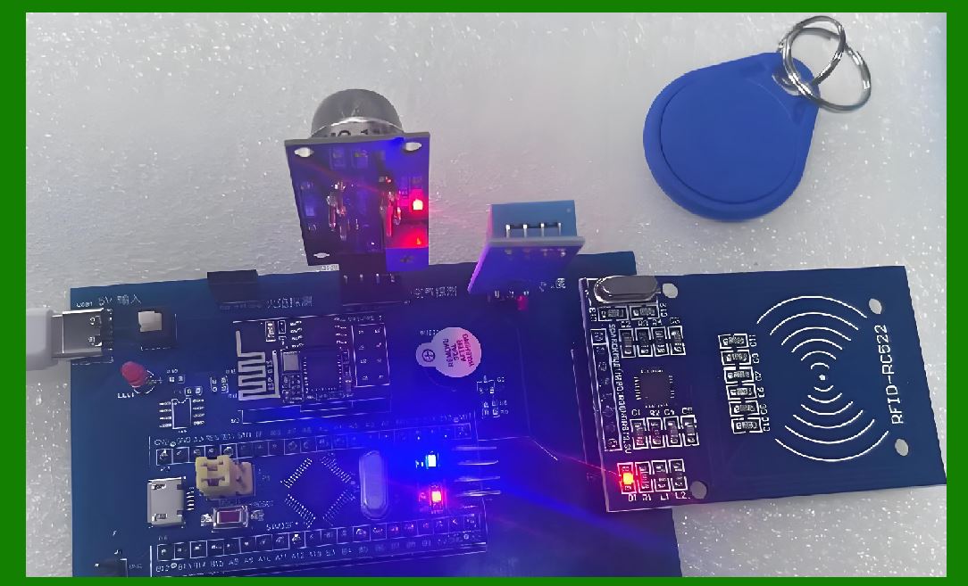
Moreover, this hybrid model represents an important step toward intelligent perception systems ¡ª systems that can ¡°understand¡± the physical behavior of objects in real time and adjust their sensing strategies accordingly. |
|
9. Motion Detection and Tracking Fundamentals |
9.1 |
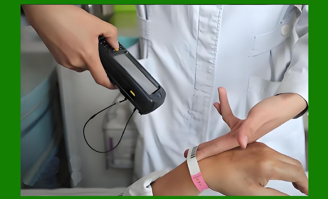
For a hybrid identification system to dynamically predict the motion state of objects, it must first be able to detect and track motion precisely. The detection process involves identifying when an object enters, stays within, and exits the reading zone. The tracking process involves continuously monitoring its speed, trajectory, and orientation during that time. |
9.2 |
A combination of sensors is typically used for this purpose. Common sensors include infrared proximity detectors, ultrasonic sensors, laser rangefinders, optical encoders attached to conveyor belts, and high-speed cameras for vision-based tracking. The system doesn¡¯t depend on a single sensor type; instead, it fuses multiple data streams to obtain a robust motion profile. |
9.3 |
For instance, infrared sensors provide quick detection when an object crosses a threshold, while laser sensors provide precise distance and size measurements. High-speed cameras, on the other hand, can calculate motion vectors by comparing successive image frames. |
9.4 |
As soon as an object is detected, the control system assigns it a temporary identity ¡ª often called a motion tracking ID ¡ª used internally to associate RFID and barcode readings that occur during its transit. This ensures that even when multiple objects are present, the system can distinguish their data streams. |
9.5 |
The motion detection stage also estimates the orientation of the item. Orientation is critical because barcode reading depends heavily on label visibility, while RFID reading may be affected by antenna direction or shielding from metal surfaces. By estimating how the object is positioned, the system can infer which technology has a better chance of success. |
|
10. Motion Prediction and Behavior Modeling |
10.1 |
After detecting the object, the next stage is motion prediction ¡ª forecasting where and how it will move in the near future. Unlike simple tracking, prediction allows the system to anticipate changes and make decisions before they occur. |
10.2 |
The prediction mechanism is based on the continuous collection of speed, position, and acceleration data from sensors. Using this data, the system can construct a short-term trajectory model that estimates the object¡¯s future position in fractions of a second. |
10.3 |
For example, if the system observes that an object¡¯s speed is decreasing gradually, it can predict that the object may stop within a certain distance. This prediction triggers the intelligent switching mechanism to prepare the barcode reader for activation, since stationary or slow-moving objects are ideal for optical scanning. |
10.4 |
In contrast, if the object¡¯s acceleration increases and its predicted passing time through the scanning zone is very short, the system can favor RFID reading. The RFID subsystem can operate effectively even at high speeds because it doesn¡¯t require precise alignment or visibility. |
10.5 |
To achieve this predictive ability, modern hybrid systems use embedded microcontrollers or edge computing units that execute continuous calculations at millisecond intervals. These units apply smoothing and filtering to raw sensor data to eliminate noise and ensure that predictions remain stable. |
10.6 |
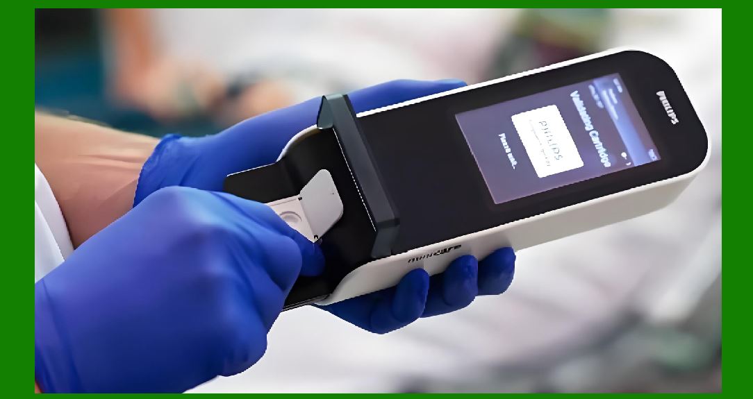
Prediction accuracy is crucial for timing control. If the system misjudges the speed or timing, the scanner may attempt to read the barcode too early or too late, resulting in a missed scan. By refining its predictions using feedback from prior readings, the system continually improves its accuracy ¡ª a process known as adaptive motion learning. |
|
11. Sensor Fusion and Data Correlation |
11.1 |
One of the key strengths of hybrid RFID-barcode systems lies in sensor fusion ¡ª the technique of combining data from multiple heterogeneous sensors to derive a unified understanding of the object¡¯s behavior and environment. |
11.2 |
For example, a system might use: |
A laser distance sensor to measure the object¡¯s distance from the reader. |
An optical camera to detect barcode label orientation. |
An RFID signal analyzer to measure signal strength and phase angle, which can indirectly estimate object position. |
A motion encoder on the conveyor to provide precise speed data. |
11.3 |
Each of these sensors provides partial information. When fused together, they allow the decision engine to reconstruct a complete motion and context profile. The data fusion process usually follows three steps: |
Temporal alignment ¡ª ensuring all sensor data corresponds to the same moment in time. |
Normalization ¡ª converting different sensor readings into comparable scales. |
Integration ¡ª merging them into a consistent, unified motion estimate. |
11.4 |
For example, suppose a laser sensor measures that the object is 40 cm away from the reading gate, while the encoder shows a belt speed of 1 m/s. The system can then predict that the object will reach the scanning point in 0.4 seconds. Meanwhile, the RFID subsystem reports weak signal strength, indicating that the tag is not optimally oriented. The system combines this information to decide that barcode scanning should be attempted instead. |
11.5 |
Sensor fusion also improves fault tolerance. If one sensor fails or provides unreliable data ¡ª such as a camera being blinded by glare ¡ª other sensors can compensate. This redundancy ensures consistent performance even in harsh or unpredictable environments. |

|
12. RFID Reading Process in Hybrid Mode |
12.1 |
When the system determines that RFID reading is optimal, it activates the RFID subsystem. The reader transmits electromagnetic waves through its antenna to power and communicate with nearby tags. |
12.2 |
The system dynamically adjusts parameters such as transmit power, frequency hopping, and antenna polarization depending on motion prediction. If the object is expected to move quickly through the field, the reader increases power output and broadens its read zone to maximize coverage. |
12.3 |
As the tag enters the electromagnetic field, it reflects modulated signals back to the reader. The reader decodes these signals to extract the tag¡¯s ID and any stored data, such as batch number or manufacturing date. |
12.4 |
In joint systems, RFID reading is often enhanced with spatial localization. By analyzing the received signal strength or phase, the system can estimate the tag¡¯s relative position within the field. This spatial awareness helps correlate RFID data with visual data from barcode cameras, ensuring that both readings refer to the same physical item. |
12.5 |
Once an RFID read is confirmed, the system cross-verifies it with previous motion predictions. If the reading occurred earlier or later than expected, the system adjusts its prediction model for subsequent objects, continuously improving performance. |
12.6 |
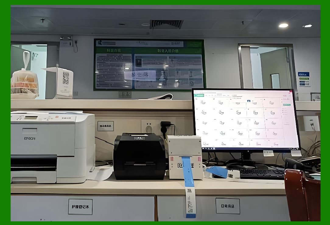
In some cases, multiple RFID antennas are positioned at different angles. As motion prediction indicates an approaching object, the system selectively activates the antenna most likely to have optimal coverage. This minimizes interference and energy consumption. |
|
13. Barcode Reading Process in Hybrid Mode |
13.1 |
When the system determines that barcode scanning is more appropriate ¡ª such as when an object slows down or comes to rest ¡ª it activates the barcode subsystem. |
13.2 |
Barcode scanning involves optical image capture followed by pattern decoding. Depending on system design, this may use a laser line scanner or a camera-based imager. Camera-based systems can decode multiple barcode types, including 1D and 2D codes. |
13.3 |
Before scanning begins, the decision engine checks several optical conditions, including illumination intensity, angle of incidence, and focus distance. These parameters are adjusted in real time to match predicted object position and speed. |
13.4 |
If the motion prediction unit expects slight vibration or movement, the system increases exposure speed or activates image stabilization. Conversely, if the object is predicted to remain still for a moment, the system can use higher-resolution imaging to capture more detailed code patterns. |
13.5 |
When the barcode is decoded, its data is compared with any RFID tag data previously associated with the same motion tracking ID. If both match, the result is marked as ¡°verified,¡± improving confidence in identification accuracy. |
13.6 |
In environments where light reflections or smudges may affect readability, the hybrid system can perform multi-angle barcode capture. Cameras at different orientations are triggered based on motion predictions to ensure at least one successful scan. |

|
14. Dynamic Decision Loop |
14.1 |
The dynamic decision loop is the continuous cycle that governs how the system predicts, switches, and confirms identification modes. |
14.2 |
Each loop iteration typically occurs in milliseconds, allowing real-time reaction to motion changes. The decision engine continually receives inputs such as: |
Object speed and direction. |
Object distance from reading points. |
RFID signal quality metrics. |
Barcode visibility probability. |
Environmental parameters (light level, radio interference). |
14.3 |
Based on this information, it classifies the current situation into one of several decision states, such as: |
RFID priority mode. |
Barcode priority mode. |
Combined mode (read both). |
Idle or waiting mode (no object detected). |
14.4 |
In RFID priority mode, the barcode scanner remains in standby, conserving energy but ready to activate instantly if the RFID signal fails. In barcode priority mode, the RFID reader reduces power to minimize radio noise but remains synchronized with motion tracking. |
14.5 |
The system¡¯s control algorithm continuously evaluates performance feedback. If RFID success rate drops below a threshold due to interference, it shifts more weight to barcode scanning, and vice versa. This adaptability ensures long-term stability without manual recalibration. |
14.6 |
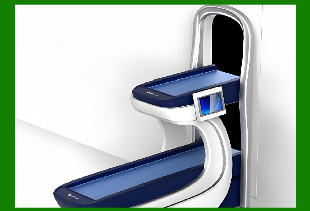
This decision loop is essentially a closed feedback system ¡ª its output (scanning success or failure) becomes the input for the next iteration. Over time, the system ¡°learns¡± environmental and operational patterns, refining its predictive accuracy. |
|
15. Environmental Awareness and Adaptation |
15.1 |
A key advantage of intelligent joint reading systems is environmental adaptability. Real-world conditions such as lighting, radio interference, or object surface texture can drastically influence identification success. |
15.2 |
To handle this, environmental sensors continuously monitor ambient light, temperature, and electromagnetic noise. This data is sent to the decision engine, which dynamically compensates by adjusting system parameters. |
15.3 |
For instance, in bright sunlight, camera exposure may need to shorten to prevent overexposure, while RFID readers might need to slightly shift frequency bands to avoid interference. Conversely, in dark or enclosed areas, the system increases illumination intensity for barcode scanning. |
15.4 |
Environmental adaptation also extends to surface reflectivity. Glossy or metallic packaging can cause barcode scanners to misread. The system detects this by analyzing image reflection patterns and, if necessary, triggers RFID reading instead. |
15.5 |
Through this continuous adaptation, the hybrid system achieves robust performance across diverse scenarios, from outdoor logistics yards to high-speed factory lines. |
|
16. Synchronization Between RFID and Barcode Data |
16.1 |
For joint reading to work effectively, both RFID and barcode subsystems must share a common data synchronization framework. This ensures that readings from both technologies refer to the same physical object at the same moment. |
16.2 |
Synchronization is managed through the motion tracking ID assigned earlier. Each sensor reading ¡ª RFID or barcode ¡ª includes a timestamp and spatial position estimate, allowing the central controller to merge them correctly. |
16.3 |
When both RFID and barcode results are available, the system performs a data matching process. If the two identifiers correspond to the same product code or serial number, the system confirms identification success. If discrepancies occur, it may flag the item for re-verification. |
16.4 |
This dual validation greatly enhances reliability. Even if one technology produces a partial or uncertain result, cross-referencing the other provides confidence. It also allows error detection, such as identifying mislabeled or duplicate-tagged items. |
16.5 |
Synchronization also enables performance analytics. The system logs each successful or failed read, allowing operators to monitor trends and optimize equipment placement over time. |
|
17. Energy Management and Efficiency |
17.1 |
Another important consideration in hybrid systems is energy efficiency. Operating both RFID and barcode readers continuously could consume excessive power, especially in large-scale installations. |
17.2 |
The intelligent control unit therefore implements adaptive power management. Based on motion prediction, it only activates each subsystem when necessary. |
17.3 |
For example, if the system predicts that an object will remain in the scanning zone for 0.5 seconds, the RFID reader may only transmit during the last 0.3 seconds ¡ª precisely when the tag is within optimal range. The barcode scanner may activate slightly earlier to prepare illumination and focus. |
17.4 |
In idle periods with no detected motion, the system powers down nonessential modules. Sensors remain active in low-power mode to detect the next approaching object. This design allows continuous operation with minimal energy waste. |
17.5 |
Smart energy management is especially valuable in mobile or battery-powered devices, such as handheld hybrid scanners or autonomous robots that rely on onboard power. |

|
18. Software Architecture and Control Logic |
18.1 |
The intelligence of hybrid systems is driven primarily by software architecture. The control software integrates data acquisition, prediction algorithms, and decision-making logic into a coordinated framework. |
18.2 |
At the lowest level, hardware interface drivers handle communication with sensors and readers. The mid-level data processing layer filters noise, synchronizes timestamps, and computes derived quantities such as velocity and signal quality. |
18.3 |
Above that lies the decision engine, which executes the dynamic switching logic described earlier. It uses predefined rules, adaptive learning, and real-time feedback to choose the optimal scanning mode. |
18.4 |
A supervisory layer oversees overall operation, maintaining logs, reporting system health, and allowing remote configuration through network interfaces. |
18.5 |
The architecture is modular, allowing upgrades or reconfiguration. For instance, new sensors or machine learning modules can be added without redesigning the entire system. |
|
19. Communication and Data Integration |
19.1 |
In industrial environments, hybrid identification systems rarely operate in isolation. They form part of a larger data integration ecosystem, connecting to warehouse management systems (WMS), manufacturing execution systems (MES), or enterprise resource planning (ERP) platforms. |
19.2 |
Communication occurs via standard protocols such as Ethernet, Wi-Fi, or serial interfaces. Data packets include object identifiers, timestamps, sensor readings, and confidence scores. |
19.3 |
By integrating RFID and barcode results into enterprise databases, the system enables complete traceability ¡ª from production to shipment. Each item¡¯s movement can be tracked across facilities, ensuring accountability and transparency. |
19.4 |
This integration also supports analytics, enabling organizations to analyze throughput, detect bottlenecks, and optimize layout based on motion prediction performance. |
|
20. Example of Predictive Switching in Action |
20.1 |
Consider a sorting system at an e-commerce fulfillment center. Packages arrive randomly, with varying shapes and materials. Some boxes have RFID tags embedded under tape, while others have barcodes printed on labels. |
20.2 |
As each package approaches the scanning gate, motion sensors detect speed and orientation. One package is predicted to pass through in just 0.25 seconds ¡ª too fast for accurate barcode scanning. The decision engine activates RFID reading as the primary mode. |
20.3 |
Another package is predicted to pause briefly because the conveyor segment ahead is congested. The system switches to barcode scanning, capturing a high-resolution image of the label. RFID remains in standby. |
20.4 |
In a third case, the system predicts moderate speed but observes strong glare on the barcode surface. It decides to read both RFID and barcode simultaneously, using whichever result confirms first. |
20.5 |
All these operations occur automatically, with each decision made in milliseconds, ensuring that every package is identified correctly without manual supervision. |

|
21. Advanced Predictive Algorithms |
21.1 |
The heart of a dynamic joint reading system lies in its predictive algorithms, which transform raw sensor data into actionable insights about object motion and environmental dynamics. These algorithms analyze time-series data from sensors and readers, predict short-term future states, and guide the decision engine to act preemptively. |
21.2 |
At the simplest level, the prediction mechanism can use linear extrapolation, where current speed and direction are assumed to continue for a short time. For example, if a package is moving at 1.5 m/s and shows no acceleration, the system predicts it will reach the scanning point after a fixed delay. |
21.3 |
More advanced systems use adaptive filtering techniques that continuously refine estimates. For instance, a Kalman filter or a similar statistical estimator smooths noisy measurements and predicts future states by modeling both measurement uncertainty and motion dynamics. |
21.4 |
Some modern industrial systems apply behavioral motion models derived from previous operational data. By analyzing patterns from thousands of items passing through the system, they can anticipate common trajectories, such as gradual slowing near curves or sudden accelerations when conveyors merge. |
21.5 |
Predictive algorithms also consider non-motion parameters, such as lighting conditions, radio field interference, or equipment temperature. If environmental sensors detect conditions that might degrade barcode readability, the system preemptively switches to RFID before a failure occurs. |
21.6 |
These algorithms are not static. They learn over time, automatically adjusting to new motion patterns, seasonal lighting changes, or hardware wear. Continuous adaptation allows hybrid systems to maintain high performance without manual recalibration. |

|
22. Machine Learning for Intelligent Decision-Making |
22.1 |
Modern hybrid systems increasingly employ machine learning (ML) to enhance their decision-making capability. Instead of relying only on rule-based logic, ML algorithms can identify complex relationships between sensor inputs and reading success rates. |
22.2 |
A supervised learning approach can be used during system setup. Historical data ¡ª including motion speeds, object sizes, RFID signal strengths, and barcode visibility scores ¡ª is labeled with successful or failed reading outcomes. The model learns which combinations lead to success for each mode. |
22.3 |
Once trained, the ML model operates in real time, predicting the probability of success for each identification method under current conditions. The decision engine then selects the mode with the highest predicted success probability. |
22.4 |
For instance, the system might learn that objects moving faster than 1.2 m/s under bright lighting and high radio interference have a 90% RFID success rate but only a 30% barcode success rate. This knowledge allows it to make optimal decisions even in new environments. |
22.5 |
Reinforcement learning can further refine behavior. The system treats each identification event as an experiment: successful reads yield positive feedback, while failures yield negative feedback. Over time, it learns the best policy for switching modes under dynamic, uncertain conditions. |
22.6 |
By incorporating ML, the hybrid system effectively gains a form of situational awareness ¡ª the ability to interpret complex real-world inputs and adapt intelligently without explicit programming. |

|
23. Multi-Object Recognition and Tracking |
23.1 |
In industrial settings, multiple objects often pass through a scanning zone simultaneously. This creates a challenge known as multi-object tracking ¡ª ensuring that each RFID or barcode read corresponds to the correct physical object. |
23.2 |
The motion sensing subsystem addresses this by assigning a unique motion tracking ID to each detected object upon entry. This ID is maintained as the object moves through the system. |
23.3 |
The control unit tracks each ID¡¯s trajectory independently, predicting when it will enter and exit the read zones. RFID and barcode data are tagged with these IDs, allowing precise matching. |
23.4 |
However, when multiple RFID tags respond simultaneously, collision management becomes necessary. RFID readers use anti-collision protocols to identify tags one by one, even when multiple are present. Motion prediction assists by estimating which tag is physically closest, reducing ambiguity. |
23.5 |
In parallel, machine vision can identify and separate objects visually. If two packages overlap or partially obscure each other, the system uses edge detection and motion segmentation algorithms to distinguish them and assign correct IDs. |
23.6 |
By combining radio-based and optical tracking with predictive timing, the system ensures that each item¡¯s data remains correctly associated throughout its journey, preventing cross-contamination of identification results. |
|
24. Handling Complex Motion Patterns |
24.1 |
Not all objects move in straight lines at constant speeds. Some may rotate, swing, or bounce due to irregular conveyor motion or manual handling. These complex motion patterns pose difficulties for both RFID and barcode systems. |
24.2 |
For rotating items, the system monitors angular velocity using vision sensors or gyroscopic modules. If a barcode is predicted to face the scanner intermittently, the decision engine waits for the optimal rotation phase before attempting a scan. |
24.3 |
RFID, while less affected by rotation, can still experience variable signal strength depending on antenna orientation. Predictive modeling helps adjust antenna selection or transmission timing to compensate. |
24.4 |
In environments with oscillating or swinging movement, such as suspended goods on hangers, the system uses motion smoothing algorithms to identify stable intervals where reading success is most likely. Scanning attempts are timed to coincide with these stable periods. |
24.5 |
The key principle is anticipation: by continuously predicting motion rather than reacting to it, the hybrid system maintains high identification accuracy even in irregular or unpredictable motion conditions. |
|
25. Error Detection and Recovery Mechanisms |
25.1 |
No identification system is perfect. Even with prediction and adaptation, occasional read failures or mismatches can occur. The hybrid system therefore incorporates error detection and recovery mechanisms to maintain data integrity. |
25.2 |
If both RFID and barcode readings fail, the system stores a ¡°pending¡± record linked to the motion tracking ID. It may attempt a second read in a downstream station or trigger an alert for manual verification. |
25.3 |
If RFID and barcode results conflict ¡ª for instance, if they report different product IDs ¡ª the system compares both against the expected database entries. The result that matches stored metadata (such as batch or size) is accepted, and the discrepancy is logged. |
25.4 |
Repeated failures trigger adaptive responses. The system analyzes the cause ¡ª such as excessive speed, poor lighting, or interference ¡ª and modifies its parameters automatically. Over time, this feedback loop minimizes the same type of error recurring. |
25.5 |
The system also supports redundancy by saving multiple readings of the same object. If one read is unclear, previous or subsequent readings can fill the gap. |
25.6 |
By combining prediction, cross-verification, and error recovery, hybrid systems achieve reliability levels far beyond those of standalone RFID or barcode solutions. |
|
26. Data Logging and Performance Analytics |
26.1 |
Every hybrid identification system maintains detailed data logs that capture the performance of each component. Each read event includes timestamps, motion parameters, environmental data, and reading success or failure indicators. |
26.2 |
These logs form the basis for performance analytics, allowing operators to understand long-term trends. For example, they can identify which conveyor speeds produce the highest success rates or how seasonal lighting changes affect barcode scanning. |
26.3 |
The analytics module can automatically generate optimization recommendations, such as repositioning antennas or adjusting lighting angles. These insights continuously enhance efficiency. |
26.4 |
Over months or years, performance analytics also provide predictive maintenance capabilities. If RFID signal quality gradually declines, the system can alert operators that an antenna may be deteriorating before complete failure occurs. |
26.5 |
This analytical feedback transforms the identification system from a reactive tool into a self-improving platform capable of evolving through data-driven optimization. |
|
27. Integration with Industrial Automation Systems |
27.1 |
Hybrid identification systems rarely operate in isolation; they are integrated into automation control networks that manage entire production or logistics operations. |
27.2 |
Integration allows real-time communication with programmable logic controllers (PLCs), robotic arms, sorters, and warehouse management systems. When an object is identified, the system can immediately trigger sorting actions or inventory updates. |
27.3 |
For example, if an RFID read confirms a shipment destined for a specific region, the conveyor control system automatically diverts it to the correct chute. Barcode verification acts as a backup for confirmation. |
27.4 |
The integration is made possible by standardized industrial protocols such as OPC UA, Modbus TCP, or EtherNet/IP, which allow seamless data exchange between devices from different manufacturers. |
27.5 |
This unified communication environment ensures that predictive identification results directly influence operational decisions ¡ª a key element of smart factories and intelligent logistics networks. |
|
28. Human-Machine Interaction and System Visualization |
28.1 |
Despite its high level of automation, the hybrid system includes interfaces for human monitoring and control. These interfaces provide operators with visual dashboards displaying real-time data. |
28.2 |
On-screen indicators show active modes (RFID or barcode), current object speeds, and identification success rates. Color-coded alerts signal environmental issues like low illumination or strong radio interference. |
28.3 |
Operators can manually override mode switching if necessary, for example, during equipment testing. However, under normal operation, the system functions autonomously. |
28.4 |
Historical charts display motion trends, enabling users to review system performance over time. This transparency builds trust in automated decision-making and helps technicians fine-tune sensors or reading angles. |
28.5 |
By merging automation with intuitive visualization, hybrid systems maintain both machine efficiency and human oversight. |
|
29. Network and Cloud Connectivity |
29.1 |
In large-scale operations spanning multiple facilities, hybrid systems are connected via industrial networks and cloud platforms. Each station¡¯s data contributes to a centralized information system. |
29.2 |
Cloud connectivity allows remote monitoring and analytics. Managers can access dashboards from any location, reviewing identification rates, error trends, and environmental statistics. |
29.3 |
Aggregated data from multiple sites can feed into global optimization algorithms, identifying systemic patterns such as recurring signal interference or consistent barcode degradation in certain packaging materials. |
29.4 |
The cloud also facilitates software updates and AI model retraining. As environmental conditions evolve, new prediction models can be deployed remotely without halting operations. |
29.5 |
Such connectivity transforms traditional reading systems into intelligent, distributed networks ¡ª integral components of the Internet of Things (IoT) for industrial identification. |
|
30. Scalability and Modular Design |
30.1 |
Hybrid systems are designed with modularity in mind to accommodate different operational scales. A small warehouse might use a single scanning gate, while a global distribution center could deploy hundreds. |
30.2 |
Each module operates autonomously, handling local motion prediction and decision-making. Higher-level controllers coordinate data aggregation and synchronization across modules. |
30.3 |
This design ensures scalability ¡ª new reading stations can be added without reconfiguring the entire system. Each new unit automatically learns from shared data and contributes to collective intelligence. |
30.4 |
Scalability also applies to data volume. The architecture supports real-time data streaming and long-term archiving without performance loss, even when millions of objects are processed daily. |
30.5 |
Through modular expansion and distributed intelligence, hybrid systems can evolve alongside growing industrial demands. |
|
31. Case Study: Automated Postal Sorting Center |
31.1 |
A national postal service implemented a hybrid RFID-barcode reading system for parcel tracking. Each parcel carried both an RFID tag and a barcode label. |
31.2 |
As parcels traveled on high-speed conveyors, motion sensors monitored their approach. The system predicted which parcels would move too quickly for optical scanning and switched to RFID mode. |
31.3 |
When parcels slowed at diverter points, barcode readers activated to visually confirm identification. RFID remained in standby, conserving energy. |
31.4 |
Over time, the system¡¯s AI learned typical motion patterns in each zone. It optimized timing and illumination, reducing overall misread rates from 3% to less than 0.1%. |
31.5 |
The result was faster throughput, fewer manual rescans, and improved traceability across the postal network ¡ª demonstrating the practical value of dynamic hybrid reading. |
32. Case Study: Smart Manufacturing Assembly Line |
32.1 |
In an electronics assembly plant, each product tray carried an RFID tag for batch identification and a barcode label for individual component tracking. |
32.2 |
As trays moved between assembly stations, the hybrid system used RFID to identify batch codes without stopping the line. When trays paused at inspection points, barcode cameras captured detailed part numbers. |
32.3 |
Predictive motion control allowed the system to anticipate when each tray would stop or move, ensuring timely switching between modes. |
32.4 |
This dynamic operation prevented bottlenecks and eliminated mislabeling. It also synchronized automatically with robotic assembly arms through networked controllers. |
32.5 |
The hybrid approach thus enhanced both speed and precision ¡ª essential qualities in high-tech manufacturing environments. |
33. Case Study: Pharmaceutical Supply Chain |
33.1 |
In pharmaceutical logistics, strict traceability is mandatory. A hybrid identification system ensures every medicine package is verifiably tracked. |
33.2 |
Each box includes an RFID tag encoded with batch and expiration data, plus a barcode for regulatory compliance. |
33.3 |
During high-speed packaging, RFID performs mass reading. At inspection and shipping stages, barcode scanning confirms individual serials. Predictive algorithms coordinate timing to prevent read overlap. |
33.4 |
Environmental sensors monitor humidity and temperature, ensuring optimal performance of both radio and optical systems. Data is automatically uploaded to a secure cloud traceability platform. |
33.5 |
This combination of predictive control, redundancy, and regulatory transparency forms a robust solution for one of the most demanding industries. |
34. Robustness Against Environmental Challenges |
34.1 |
Factories and warehouses are rarely pristine. Dust, temperature shifts, radio interference, and vibration all challenge identification systems. |
34.2 |
The hybrid approach provides resilience. When one technology¡¯s performance drops, the other compensates automatically. |
34.3 |
If dust obscures a barcode, RFID continues to operate. If metallic shelving blocks radio waves, the barcode scanner takes over. Motion prediction ensures the correct switch happens before a read failure. |
34.4 |
Such robustness allows hybrid systems to function reliably in harsh conditions ¡ª from refrigerated logistics centers to outdoor cargo yards. |
34.5 |
This adaptability significantly reduces downtime and maintenance costs compared to single-technology solutions. |
|
35. Maintenance and Calibration Procedures |
35.1 |
Even with intelligent adaptation, periodic maintenance ensures long-term stability. The system includes self-diagnostic routines that continuously assess sensor health and alignment. |
35.2 |
If a barcode camera¡¯s focus drifts or an RFID antenna¡¯s output weakens, the system detects deviations from normal performance patterns and alerts operators. |
35.3 |
Automated calibration cycles can realign cameras and retune antennas based on motion prediction feedback, often without manual intervention. |
35.4 |
These self-maintenance capabilities reduce the need for technician visits and enable continuous 24/7 operation. |
35.5 |
Predictive maintenance ¡ª anticipating faults before they cause downtime ¡ª is a key advantage of data-driven hybrid systems. |
36. Cybersecurity and Data Protection |
36.1 |
Since hybrid systems are network-connected, data security is a critical consideration. Unauthorized access could compromise inventory data or system control. |
36.2 |
To prevent this, systems use encrypted communication, authentication protocols, and secure firmware updates. Access to control panels is restricted by user permissions. |
36.3 |
Cloud-linked hybrid systems also comply with data protection standards, ensuring that customer or product data is stored and transmitted securely. |
36.4 |
Regular security audits and intrusion detection further safeguard against malicious interference. |
36.5 |
These measures ensure that advanced automation does not come at the expense of data integrity. |
|
37. Real-Time Diagnostics and Feedback Control |
37.1 |
Real-time diagnostics continuously monitor sensor performance, RFID signal strength, barcode clarity, and environmental stability. |
37.2 |
When anomalies occur ¡ª such as fluctuating signals or poor image contrast ¡ª the feedback controller immediately adjusts parameters like antenna gain, light intensity, or camera exposure. |
37.3 |
This instant self-correction prevents temporary disturbances from escalating into read failures. |
37.4 |
The diagnostic system also records every intervention, providing traceable records for quality assurance and process auditing. |
37.5 |
Continuous diagnostics form the nervous system of hybrid identification, maintaining operational equilibrium. |
|
38. Future Developments in Hybrid Identification |
38.1 |
Future hybrid systems will incorporate edge AI processors capable of running deep learning models directly within scanners. These models will predict complex motion behaviors and optimize switching decisions in microseconds. |
38.2 |
Emerging multi-frequency RFID will further improve reading reliability across materials, while next-generation hyperspectral cameras will read damaged or low-contrast barcodes with ease. |
38.3 |
Integration with robotic vision systems will allow dynamic focusing and automatic repositioning of scanners to follow moving objects precisely. |
38.4 |
Hybrid readers may also evolve into universal identification units, capable of simultaneously handling RFID, barcodes, and new optical or acoustic codes. |
38.5 |
Ultimately, the convergence of sensing, prediction, and AI will lead to fully autonomous identification ecosystems, eliminating manual intervention altogether. |
|
39. Broader Implications for Industry and Society |
39.1 |
Beyond logistics, hybrid identification has implications for retail automation, healthcare, transportation, and smart cities. |
39.2 |
Retail stores can use predictive hybrid scanners to identify products instantly during checkout or inventory audits. Hospitals can ensure medication traceability with automatic mode switching in sterile environments. |
39.3 |
In transportation, hybrid systems can track cargo across multimodal routes ¡ª air, land, and sea ¡ª maintaining continuity of data despite environmental differences. |
39.4 |
These technologies collectively contribute to the global movement toward transparent, intelligent supply chains, where every physical item is digitally visible from origin to destination. |
39.5 |
This deep integration of physical and digital systems marks a major step toward the realization of the Internet of Everything, where identification, prediction, and decision-making occur seamlessly. |
|
40. Conclusion |
40.1 |
The joint reading of RFID and barcodes represents a technological harmony between two powerful identification methods. By combining radio and optical sensing with dynamic motion prediction and intelligent switching, the system achieves performance unattainable by either technology alone. |
40.2 |
Through sensor fusion, predictive algorithms, environmental awareness, and adaptive learning, hybrid systems deliver fast, accurate, and reliable identification even under constantly changing conditions. |
40.3 |
They reflect the essence of modern automation ¡ª systems that do not merely react but anticipate, understand, and evolve. |
40.4 |
From warehouses to production lines and from healthcare to global logistics, the principles of dynamic RFID-barcode integration will continue to shape the future of intelligent identification systems. |
40.5 |
In summary, the working principle of RFID and barcode joint reading can be described as a real-time symbiosis between sensing and intelligence: a system that observes motion, predicts outcomes, and decides ¡ª faster than any human could ¡ª which mode to use, ensuring flawless operation in the complex, dynamic world of modern industry. |
 cs@easiersoft.com