Chapter 52: RFID's Challenge - Interference and Materials |
Executive Summary |
Radio Frequency Identification (RFID) and barcodes represent two fundamentally different approaches to automatic identification and data capture. While RFID offers the advantage of non-line-of-sight reading and the ability to store more data, it faces a critical physical limitation: performance degradation when tags are placed on or near metal surfaces and liquid-containing materials. This chapter explores the physics behind this interference, its practical implications across multiple industries, and why barcodes---particularly Code 39---remain indispensable in environments where RFID struggles. Through real-world case studies from manufacturing, tire production, steel processing, and solar panel fabrication, we examine how organizations strategically deploy both technologies to leverage their respective strengths. The chapter concludes with a comprehensive summary of best practices for selecting between RFID and barcode solutions based on environmental conditions and application requirements. |

|
1. Introduction: The Fundamental Difference |
Imagine walking through a modern factory. On one conveyor belt, plastic pallets move smoothly past an RFID reader, their tags instantly transmitting data about contents and destination. On another line, metal engine blocks progress through assembly, each bearing a printed barcode that a worker scans with a handheld device. This scene captures a fundamental reality of industrial identification: RFID and barcodes are not competitors but complements, each with distinct advantages and limitations. |
The most significant limitation facing RFID technology is its interaction with certain materials. Metal surfaces reflect and absorb radio waves, while water and other liquids attenuate RF signals. These physical phenomena can render RFID tags unreadable just when they are needed most. Barcodes, by contrast, rely on optical contrast between dark bars and light spaces. They are entirely unaffected by the material to which they are attached---as long as the printed symbol remains visible and undamaged. |
This chapter examines this crucial distinction and its practical implications. We will explore the physics of RFID interference, survey real-world applications across diverse industries, and highlight the enduring role of Code 39---a barcode symbology developed in 1975 that continues to thrive in industrial environments precisely because of its reliability and simplicity. |
|
2. Understanding RFID Interference: The Physics of Frustration |
2.1 How RFID Works |
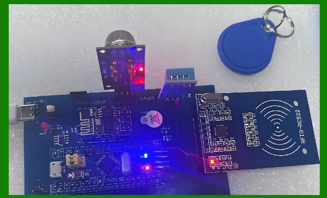
Before examining interference, we must briefly review RFID operation. A typical passive UHF RFID system consists of three components: a tag with an antenna and microchip, a reader with its own antenna, and a host system that processes the data. The reader transmits RF energy that powers the tag through induction or backscatter. The tag modulates this energy to transmit its stored information back to the reader. |
This elegant mechanism depends critically on the interaction between the tag antenna and the surrounding electromagnetic field. When the tag is suspended in free air, the antenna design matches the reader frequency, enabling efficient energy transfer and reliable communication. |
2.2 The Metal Problem |
Metal surfaces present a formidable obstacle to RFID performance through several mechanisms. |
First, metal reflects RF energy. When a tag is placed directly on a metal surface, the reflected waves interact with the incident waves, creating standing wave patterns that can cancel the signal at the tag antenna. This phenomenon, known as destructive interference, dramatically reduces the energy available to power the tag chip. |
Second, metal detunes the tag antenna. RFID tag antennas are carefully designed to resonate at specific frequencies---typically 865-868 MHz in Europe and 902-928 MHz in North America for UHF systems. When the antenna is placed near a conductive surface, the electrical characteristics change, shifting the resonant frequency away from the operating band. The tag becomes effectively invisible to the reader. |
Third, metal can act as a shield. In some configurations, the metal object may block the RF signal entirely, preventing any communication between tag and reader. |
Research has demonstrated that the primary cause of reduced read range near metal surfaces is the decrease in electric field required to meet boundary conditions at the surface . All tags show qualitatively similar degradation, though different antenna designs exhibit significant quantitative differences in performance. |
2.3 The Water and Liquid Problem |
Water presents a different but equally challenging set of issues. Liquid water has a high dielectric constant, meaning it strongly interacts with electromagnetic fields. Water molecules are polar and rotate in response to alternating electric fields, absorbing RF energy and converting it to heat. This absorption reduces the energy available to power the tag. |
Additionally, the high dielectric constant of water changes the effective electrical length of the tag antenna, again causing detuning. The severity of this effect depends on the water volume and the frequency of operation. UHF systems (860-960 MHz) are particularly vulnerable because water absorbs strongly at these frequencies, whereas LF (125-134 kHz) and HF (13.56 MHz) systems are less affected. |
The problem extends beyond pure water. Many industrial liquids, beverages, and even damp cardboard contain sufficient moisture to interfere with RFID operation. A tag on a bottle of water, for example, may fail to read reliably because the liquid inside detunes the antenna and absorbs signal energy. |
2.4 Engineering Solutions and Their Limits |
Engineers have developed various approaches to mitigate RFID interference. |
Spacer materials create physical separation between the tag and the interfering surface. By positioning the tag 5-8 mm away from metal, the electromagnetic effects diminish significantly . However, this approach has practical drawbacks: the spacer adds thickness, may not fit in tight spaces, and can complicate product design. |
Specialized antenna designs have been developed specifically for use on metal. The University of Kansas KU-Tag, for example, uses a microstrip antenna architecture that maintains performance when mounted on metal surfaces. This tag achieves consistent reads at up to 20 feet regardless of mounting surface, with a thickness of just 1.6 mm . |
On-metal tag substrates use materials such as nonwoven fabric or resin foam as a distance layer between the tag and the container . When a metal container reflects received waves, the communication distance can actually be extended because the reflective surface redirects energy back to the tag. |
Active tags with onboard batteries generate stronger signals that can overcome interference. However, these tags cost $20 to $150 each, compared to $0.50 to $1.50 for passive tags . This cost differential makes active tags impractical for many applications. |
Using the metal itself as an antenna represents an elegant solution. When an RFID chip electrically contacts a metal article, the article itself can function as the tag antenna, enabling reduced tag size and improved performance . |
Despite these innovations, no solution completely eliminates the fundamental physics of RF interaction. Specialized tags cost more, require careful placement, and still perform less reliably on metal or liquids than on other surfaces. |

|
3. Barcodes: The Unaffected Alternative |
3.1 Why Barcodes Don't Care About Materials |
Barcodes operate on an entirely different principle: optical contrast. A barcode symbol consists of dark bars and light spaces arranged in a specific pattern. The reading device illuminates the symbol and measures the reflected light. Dark bars absorb light; light spaces reflect it. The sequence of transitions between dark and light encodes the data. |
This optical mechanism is unaffected by the material beneath the barcode. A barcode printed on paper, plastic, metal, cardboard, or glass reads equally well as long as the surface provides sufficient contrast between bars and spaces. The substrate does not influence the electromagnetic properties of the reading process. |
This fundamental advantage ensures that barcodes remain the technology of choice whenever the item to be identified is metallic, contains liquid, or will be exposed to challenging environments. |
3.2 Code 39: The Industrial Workhorse |
Among the many barcode symbologies available, Code 39 holds a special place in industrial applications. Developed by Intermec Corporation in 1974 and released in 1975, Code 39 was the first barcode to encode both letters and numbers . Its enduring popularity stems from several technical characteristics that make it particularly well-suited to manufacturing and logistics environments. |
Simple encoding structure. Every Code 39 character consists of nine elements: five bars and four spaces. Among these nine elements, exactly three are wide and six are narrow . This simple binary structure (wide/narrow) makes Code 39 easy to print and decode, even with relatively low-quality printing equipment or on rough surfaces. |
Variable length. Code 39 can encode any number of characters, limited only by the physical space available for printing and the reader's scanning range . This flexibility allows manufacturers to encode serial numbers, batch information, or other data of variable length without changing symbology. |
Bidirectional scanning. Code 39 can be read from either direction, simplifying scanning operations in fast-paced industrial environments . Workers don't need to orient the symbol correctly for the scanner. |
Start and stop characters. The asterisk (*) character serves as both start and stop delimiter . This unambiguous marking helps scanners identify the beginning and end of the symbol, reducing errors. |
Optional check digit. Code 39 supports a MOD 43 check digit for applications requiring higher accuracy . This optional verification helps detect misreads in critical applications such as medical device tracking or government logistics. |
Discrete character encoding. Code 39 uses an intercharacter gap between symbols . This discrete structure makes the symbology more tolerant of printing imperfections than continuous symbologies. |
International standards. Code 39 is defined by ISO/IEC 16388 and has a corresponding Chinese national standard GB12908-91 . This standardization ensures interoperability across equipment from different manufacturers. |
Military adoption. In 1981, the U.S. Department of Defense adopted Code 39 under the LOGMARS standard (Logistics Applications of Automated Marking and Reading Symbols) . This military endorsement drove widespread adoption across defense supply chains and remains influential today. |
Limited character set. Code 39 supports 44 characters: digits 0-9, uppercase letters A-Z, and seven special characters (- . $ / + % space) . The asterisk is reserved exclusively as the start/stop character. Through full ASCII encoding, Code 39 Extended can represent all 128 ASCII characters using two-character combinations. |
Low information density. Code 39 requires more space to encode a given amount of data than more modern symbologies such as Code 128. This limitation makes Code 39 less suitable for applications requiring dense data encoding in small spaces. |
These characteristics combine to make Code 39 an ideal choice for industrial applications where reliability, simplicity, and flexibility are more important than high data density. |

|
4. Industry Applications: When to Use What |
4.1 Automotive Manufacturing: Metal Parts Need Barcodes |
The automotive industry exemplifies the complementary use of RFID and barcodes. Engine blocks, transmission housings, brake components, and other metal parts must be tracked through complex manufacturing processes. However, attaching RFID tags to these metal components presents significant challenges. |
Engine blocks, for example, have irregular surfaces and are exposed to high temperatures, cutting fluids, and mechanical impacts. An RFID tag mounted on a block would need to survive harsh conditions while maintaining reliable communication despite the metal body detuning the antenna. Specialized on-metal tags exist but increase cost and complexity. |
Barcodes printed on durable labels or directly marked on the metal surface using laser etching or dot peening provide a simple solution. The barcode remains readable throughout the manufacturing process as long as the marking remains visible. Workers scan the code at each process step, creating a complete manufacturing history without concerns about RF interference. |
Meanwhile, RFID tags are commonly placed on plastic pallets, shipping containers, and tooling fixtures. These non-metallic carriers move through the factory carrying metal parts. The RFID tag identifies the carrier and its contents, while individual parts retain barcode markings for traceability. |
This hybrid approach leverages the strengths of each technology: RFID provides bulk identification and tracking through automated reading points, while barcodes ensure individual part traceability regardless of material properties. |

|
4.2 Tire Manufacturing: The Smart ID Card System |
The tire manufacturing industry provides an illuminating example of barcode-RFID integration . Modern tire factories produce millions of tires annually, each requiring tracking through complex processes from material compounding through curing to final inspection. |
At the YongSheng Rubber 4.0 Smart Factory in Guangrao, China, every tire carries a barcode that serves as its 'smart ID card' throughout the manufacturing process . This barcode links to a comprehensive database containing all information from mixing to final assembly. Workers scan the barcode at each process step, and the system automatically verifies that the correct materials and processes have been applied. |
The barcode system provides several advantages in the tire production environment. Tires contain significant metal content (steel belts and bead wires) that would interfere with RFID operation. The curing process involves high temperatures that could damage RFID tags. The curved surface of a tire presents challenges for tag placement and readability. |
The factory also uses RFID technology, but strategically. While individual tires carry barcodes, RFID tags are placed on carriers and fixtures . The system reads these tags automatically as carriers move through the factory, triggering material handling equipment such as automated guided vehicles (AGVs). When the system detects a mismatch between materials and the correct process, it stops the line immediately, preventing defects from propagating. |
The integration extends beyond the factory floor. Consumers can scan the barcode on their tire to access production date, raw material information, and other transparency data . This consumer-facing application would be impractical with RFID, as most consumers lack RFID readers but all have smartphones with cameras. |
For internal management, the barcode system enables rapid problem resolution. When a customer claims a tire defect, the manufacturer scans the barcode and retrieves complete production data in under a minute . This capability helps identify whether the issue stems from manufacturing defects or customer misuse, streamlining warranty claims and continuous improvement efforts. |

|
4.3 Steel Pipe Manufacturing: From 4.5% Errors to Zero |
The steel processing industry offers another compelling case study in material-based technology selection . In steel coil and pipe manufacturing, tracking individual items through processing, storage, and shipment presents significant challenges. |
A study conducted at a steel pipe manufacturing facility used value stream mapping and 5Why analysis to identify operational problems. The facility experienced approximately 4.5% error rates in steel strip allocation and production, along with about 6% of customer pickups involving incorrect pipes . |
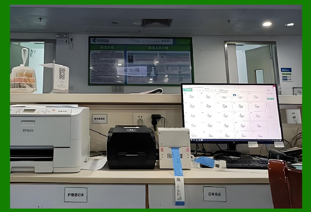
To address these issues, the researchers implemented a hybrid identification system. Barcodes provided traceability for steel coils and strips, enabling the facility to track materials from receipt through processing. RFID technology was applied to finished steel pipe identification and warehouse management, where the larger items could accommodate tags and the reading efficiency offered benefits. |
The results were dramatic. Steel strip misallocation and production errors dropped from 4.5% to zero. Incorrect customer pickups decreased from approximately 6% to zero . The facility achieved significant improvements in inventory management accuracy and operational efficiency. |
The barcode component of this solution proved essential because steel products are inherently metallic. Steel coils, strips, and pipes would block RFID signals or detune tags. By applying barcodes directly to the steel, either through labels or direct marking, the facility gained reliable identification regardless of material properties. The RFID component addressed other parts of the operation where the technology offered advantages. |
|
4.4 Solar Panel Manufacturing: Overcoming Environmental Challenges |
The photovoltaic industry has rapidly expanded, with China becoming the world's largest producer of solar cells . This industry presents unique identification challenges due to the harsh environment of solar panel manufacturing and the demanding traceability requirements of global markets. |
Traditional barcodes often fail in solar manufacturing environments. Cutting fluids, high temperatures, and abrasive particles damage printed labels, making them unreadable . Additionally, solar panels themselves contain metallic and silicon materials that could interfere with RFID operation if tags are placed incorrectly. |
A solar wafer manufacturing facility addressed these challenges through strategic technology deployment . The facility uses UHF RFID for the front end of the process, where ingots and blocks move through the production line. The longer read range of UHF RFID enables automated reading without manual scanning. For the back-end process, where precision is paramount, the facility uses HF RFID for accurate identification . |
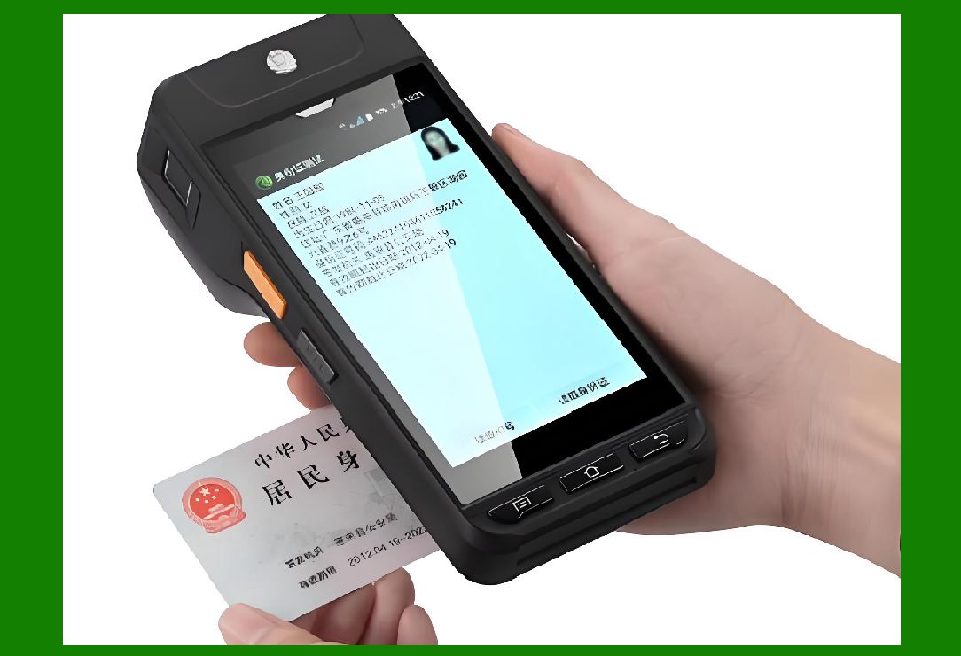
At each stage of the process, the system automatically reads tags and updates the manufacturing execution system (MES). The process begins when workers use a PDA to scan a crystal holder, entering traceability information. The holder then passes through RFID readers at various stations, automating data capture . |
This hybrid approach addresses the environmental challenges that would defeat either technology alone. RFID provides automated reading where environmental conditions permit, while barcodes remain available as backup and for applications where RFID is impractical. |
|
4.5 Aerospace and Defense: Following Military Standards |
The aerospace and defense industries have been early adopters of Code 39, driven in part by military standards . The U.S. Department of Defense adopted LOGMARS in 1981, establishing Code 39 as the standard for logistics marking across defense supply chains. |
This requirement has persisted because of the demanding conditions in which aerospace components operate. Jet engine parts, landing gear, structural components, and avionics are all metallic. Many operate at extreme temperatures that would destroy RFID tags. Some are subject to high vibration, corrosive fluids, or other harsh conditions. |
Code 39 barcodes marked directly on metal surfaces using laser etching or chemical etching provide identification that survives these conditions. The marking becomes essentially permanent, readable for the life of the component. When combined with optional check digits, the system provides exceptional accuracy. |
The aerospace industry also uses RFID, but typically for tracking high-value tools, shipping containers, and other non-metallic assets. The two technologies coexist, each serving its appropriate purpose. |

|
4.6 Healthcare and Medical Devices: Sterilization and Liquids |
Medical device manufacturing presents unique identification challenges. Surgical instruments, implants, and diagnostic equipment must be tracked through manufacturing, sterilization, and use. Many medical devices are metallic, and many contain liquids or are used in liquid environments. |
The healthcare industry has adopted multiple identification technologies, with barcodes remaining essential for items that cannot use RFID. Surgical instruments, for example, are typically made of stainless steel and undergo repeated sterilization cycles involving high heat and moisture. RFID tags would not survive these conditions, and even if they did, the metal instruments would block the RF signal. |
Barcodes etched or printed on instruments provide reliable identification that survives sterilization. The Code 39 symbology, with its simple structure and tolerance for printing imperfections, is well-suited to this application. The optional check digit provides the accuracy required for patient safety. |
The industry has developed specialized medical barcode standards that build on Code 39's foundations. These standards ensure that barcodes on medical devices are readable by standard scanners and contain standardized data elements such as lot number, expiration date, and device identifier. |
Meanwhile, RFID tags find application in non-metallic medical assets: IV pumps, patient wristbands, medication carts, and supply inventory. The choice between technologies remains driven by the physical properties of the item being identified. |

|
4.7 Logistics and Transportation: Mixed Fleets |
Logistics operations handle diverse cargo, from pallets of consumer goods to heavy machinery. RFID has become ubiquitous in logistics, particularly for tracking shipping containers, pallets, and totes. However, barcodes remain essential for identifying individual items within shipments. |
A logistics provider shipping a pallet of canned beverages illustrates the hybrid approach. The pallet carries an RFID tag that the warehouse system reads automatically, confirming the pallet's identity and routing. Within the pallet, each case carries a barcode that identifies the product, batch, and expiration date. When the pallet arrives at a distribution center, the RFID system provides bulk inventory counts, but workers may still scan individual cases to verify shipments or handle returns. |
The material challenge appears when logistics operations handle metal items. Heavy equipment, automotive parts, and industrial components all present the same metal interference problem. In these cases, barcodes provide reliable identification while RFID tracks the containers and carriers. |

|
5. Technical Deep Dive: Code 39 in the Industrial Ecosystem |
5.1 Printing and Marking Methods |
The printing method chosen for Code 39 barcodes varies by application and environment. |
Thermal transfer printing produces durable labels suitable for many industrial applications. The printer heats a ribbon that transfers ink onto the label substrate. These labels can be coated with protective laminates to resist chemicals, heat, and abrasion. |
Direct thermal printing uses heat-sensitive paper that darkens when heated. These labels are less durable than thermal transfer but adequate for short-term applications such as shipping labels. |
Laser etching creates permanent markings on metal surfaces. A laser beam removes a thin layer of material, creating contrast between the etched and unetched areas. These markings survive harsh environments and last the lifetime of the component. |
Dot peening uses a stylus to create indentations in the metal surface. The resulting pattern provides contrast that is readable by specialized barcode scanners. This method is commonly used for engine blocks and other large metal parts. |
Inkjet printing can produce barcodes on packaging and labels, though the durability varies with the ink formulation and substrate. |
5.2 Reading Equipment |
The equipment used to read Code 39 spans a similar range of capabilities. |
Handheld scanners are the workhorse of industrial barcode reading. Laser scanners can read barcodes at distances from contact to several feet, while imagers capture digital images and decode the symbol. Industrial scanners are often enclosed in rugged housings that resist drops and exposure to liquids. |
Fixed mount scanners are installed at workstations, conveyors, and portals. These scanners read barcodes as items pass, providing automated data capture without operator intervention. |
Mobile computers such as PDAs and smartphones with integrated cameras can read barcodes using image-based decoding software. This capability extends barcode reading to consumer applications and field service. |
Vision systems combine barcode reading with other inspections, such as verifying print quality, measuring dimensions, or checking labels. |
5.3 Data Content and Structure |
The data encoded in Code 39 can be structured in various ways depending on application requirements. |
Serial numbers provide unique identification of individual items. The manufacturing system maintains a database linking each serial number to production data. |
Batch and lot numbers identify groups of items produced under similar conditions. Batch numbering enables traceability for quality control and recall management. |
Part numbers identify the product type, often combined with serial numbers for individual identification. |
Date and time stamps may be encoded for time-sensitive products. |
Application identifiers (AI) as defined by GS1 standards structure the data content, enabling automatic interpretation of encoded information. |
|
6. Future Trends and Developments |
6.1 On-Metal RFID Advances |
The RFID industry continues to develop better solutions for challenging environments. The KU-Tag from the University of Kansas represents one promising direction: a passive UHF tag that works on metal and liquids without requiring special mounting or active power sources . With a thickness of 1.6 mm and manufacturing cost estimated at $0.50-$1.50, such tags could expand RFID's applicability. |
However, on-metal tags still face challenges. They cost more than standard tags, require careful design for specific applications, and may not match the reliability of barcodes in extreme conditions. The university tag's stated read range of 20 feet suggests continuing performance limitations. |
6.2 Hybrid Systems |
The trend in industrial identification is toward hybrid systems that combine multiple technologies. A typical modern factory uses: |
RFID for automated reading at portals and fixed locations |
Barcodes for individual item identification and visual verification |
Vision systems for quality inspection and label verification |
Digital twins connecting physical items to virtual representations |
Blockchain for supply chain traceability |
These technologies complement rather than compete. The optimal solution for any application depends on the physical environment, required reading distance, data capacity needs, and cost constraints. |
6.3 Direct Part Marking |
Direct part marking (DPM) techniques that create permanent marks on metal surfaces are increasingly common. Laser etching, dot peening, and electrochemical etching produce barcodes that survive harsh environments. The use of 2D symbols such as Data Matrix codes, which can be marked in small areas, complements traditional Code 39. |
6.4 Environmental Considerations |
The environmental impact of different identification technologies deserves attention. Barcodes require physical media such as labels or inks, while RFID tags contain metals and plastics. Both technologies have environmental footprints, though the trade-offs are complex and depend on specific applications. |

|
7. Selection Framework: Barcode or RFID |
Based on the analysis throughout this chapter, the following framework helps guide technology selection: |
7.1 Choose Barcode When |
The item is metallic. Metal will interfere with RFID, regardless of specialized tag designs. |
The item contains liquid. Water and aqueous solutions absorb RF energy. |
The environment is extreme. High temperatures, chemicals, or abrasion may damage RFID tags. |
Cost is critical. Barcode labels cost pennies; RFID tags cost dollars. |
Visual inspection is needed. A visible barcode allows workers to read it without equipment. |
Consumer interaction is required. Consumers have cameras but not RFID readers. |
Data capacity is modest. Code 39's limited capacity is often sufficient for serial numbers and part numbers. |
7.2 Choose RFID When |
Reading without line-of-sight is essential. RFID can read through some materials. |
Multiple tags must be read simultaneously. Batch reading greatly speeds inventory operations. |
Read distance matters. UHF RFID can read from meters away. |
Data needs updating. Read-write tags can store changing information. |
Environmental conditions permit. The item and environment don't interfere with RF communication. |
High data capacity is required. RFID tags can store more data than barcodes. |
7.3 Use Both When |
Identifying both carriers and individual items. RFID tracks pallets; barcodes track cases. |
Providing redundancy. If one technology fails, the other provides backup. |
Automating bulk reading. RFID reads automatically at portals; barcodes support manual verification. |
Managing mixed inventories. Some items suit RFID; others require barcodes. |
|
8. Comprehensive Summary |
RFID and barcodes serve complementary roles in industrial identification, with the choice between them driven primarily by the physical properties of the item being identified and the environment in which identification occurs. |
The physics of RFID interference is fundamental. Metal surfaces reflect RF energy and detune tag antennas, while water and liquids absorb RF signals and alter antenna characteristics. These effects are not merely theoretical inconveniences; they dramatically reduce RFID read range and reliability. While engineers have developed specialized on-metal tags, spacer materials, and other mitigation techniques, no solution completely eliminates the fundamental interaction between RF energy and conductive or dielectric materials. The cost and complexity of such solutions often outweigh their benefits. |
Barcodes are immune to material interference. The optical contrast mechanism underlying barcode reading is unaffected by metal, water, or other RF-interfering materials. As long as the printed symbol remains visible and undamaged, the barcode will read regardless of the substrate beneath it. This fundamental advantage ensures that barcodes remain the identification technology of choice for metallic items, liquid-containing products, and extreme environments. |
Code 39 remains the industrial barcode standard. Its simple encoding structure, variable length, bidirectional readability, and optional check digit make it ideally suited to manufacturing and logistics applications. The symbology's adoption by the U.S. Department of Defense under the LOGMARS program drove widespread acceptance that continues to this day. Its limitations---modest data capacity and low information density---are acceptable for the identification applications where it is typically deployed. |
Hybrid solutions dominate best practice. Modern manufacturing facilities deploy both RFID and barcodes strategically. RFID tags track plastic pallets, totes, and carriers that can be read automatically at portals and fixed stations. Barcodes mark individual items, particularly metallic or liquid-containing products, enabling manual scanning at workstations and final inspection. The two technologies work in concert, each performing the functions for which it is best suited. |
Industry case studies demonstrate the practical application of these principles. Automotive manufacturers use barcodes on engine blocks and other metal parts while RFID tracks plastic carriers. Tire factories give every tire a barcode ID while using RFID on carriers and fixtures. Steel pipe manufacturers reduced errors to zero through a hybrid barcode-RFID system. Solar panel producers deploy both technologies strategically across different manufacturing stages. Aerospace and defense have used Code 39 for decades under military standards. Logistics providers use RFID for pallets and barcodes for individual shipments. |

|
Future developments will expand RFID capabilities but not eliminate the fundamental physics. On-metal RFID tags continue to improve, but they still cost more and perform less reliably than standard tags in free air. Hybrid systems will likely become more sophisticated, with multiple identification technologies integrated into comprehensive digital tracking solutions. However, the material interference problem is rooted in fundamental physics that no amount of engineering can entirely eliminate. Barcodes will continue to have a place in industrial identification for the foreseeable future. |
The choice between RFID and barcodes is not a competition. Both technologies have legitimate places in the identification ecosystem. The optimal solution depends on the application: the item's material properties, environmental conditions, required reading distance, cost constraints, and operational requirements. Skilled practitioners understand both technologies and deploy each where it provides the greatest value. The goal is not to choose one technology over the other but to select the right tool for each specific application. |
Practical implications for industry professionals. Those designing identification systems should consider the material properties of items to be identified early in the design process. If the item is metallic or contains liquid, plan for barcodes or direct part marking. Use RFID for non-metallic carriers, containers, and items that can be read at a distance. Consider hybrid solutions that combine the strengths of both technologies. Select Code 39 for industrial applications where its simple encoding and wide compatibility provide advantages. Design the overall system architecture to support the chosen technologies. |
The enduring lesson. Radio waves interact with matter. Metals and water are opaque to RF energy in ways that matter for RFID performance. Barcodes, relying on the simple interaction of light and dark surfaces, operate independently of substrate material. This physical reality will continue to shape identification technology choices for the foreseeable future. The most effective identification solutions acknowledge and embrace this reality, deploying each technology where it works best rather than trying to force a single technology to solve all problems. |
 cs@easiersoft.com