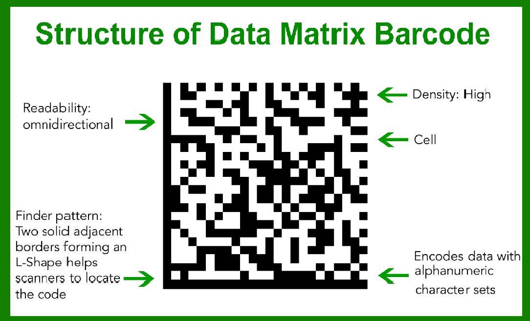
Data Matrix codes are two-dimensional barcodes that encode information in a grid of black and white cells or modules. These codes are highly efficient for storing data and are widely used in various industries for tracking and identification purposes. The Data Matrix standard is defined by several key specifications: |
General Structure |
1.Modules: Definition: The smallest unit in the Data Matrix code, typically square or round in shape. Arrangement: Modules are arranged in a grid pattern within the symbol. |
2.Symbol Size: Range: Data Matrix symbols can vary in size, typically ranging from 10x10 to 144x144 modules. Data Capacity: The size of the symbol determines its data capacity, with larger symbols capable of encoding more information. |
3.Finder Pattern: Function: Used to locate and orient the Data Matrix symbol. Appearance: A solid line along two adjacent edges of the symbol (usually the left and bottom), forming an L-shape. |
4.Timing Pattern: Function: Assists in determining the module size and shape. Appearance: Alternating black and white modules along the other two edges of the symbol (top and right). |
5.Quiet Zone: Definition: A margin around the Data Matrix symbol, free from any markings. Requirement: Ensures the symbol is distinguishable from surrounding text or graphics. |
|
Encoding Capacity |
1.Data Capacity: Numeric: Up to 3,116 numeric characters. Alphanumeric: Up to 2,335 alphanumeric characters. Binary/ASCII: Up to 1,556 bytes of binary data or ASCII characters. Extended ASCII: Capable of encoding the full ASCII character set, including extended characters. |
2.Error Correction: Algorithm: Uses Reed-Solomon error correction to ensure data integrity. Capacity: Can recover from damage or errors affecting up to 30% of the symbol. |

|
Data Regions and Format |
1.Data Regions: Definition: Areas within the symbol where data is encoded. Structure: Composed of modules arranged in a regular array. Large symbols may have multiple data regions. |
2.Module Shape: Variety: Modules may be round or square. For instance, dot-peened cells are generally round. |

|
Encoding Process |
1.Data Encapsulation: Padding: Additional padding modules are added if necessary to fill the symbol. Data Storage: Data is stored in a compact format to maximize space efficiency. |
2.Error Correction and Redundancy: Reed-Solomon Codes: Applied to provide robust error correction, allowing the symbol to be read even if parts are damaged. |
3.Reading and Decoding: Scanning Technology: Can be read using optical scanners or cameras. Decoding Software: Specialized software interprets the module pattern to extract the encoded data. |

|
Example of a Data Matrix Code Encoding 'Wikipedia' |
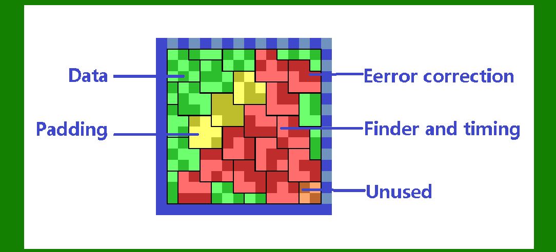
Let's illustrate a Data Matrix code encoding the text 'Wikipedia' with colored regions to highlight its different components. |
Here is a breakdown of the components and their respective colors: |
Data (Green): Modules that contain the actual encoded data. Padding (Yellow): Modules used to fill any remaining space after data is encoded. Error Correction (Red): Modules reserved for error correction data. Finder and Timing (Magenta): Modules that form the finder and timing patterns. Unused (Orange): Modules that are not used in encoding or error correction (if any). |

|
Visualization |
Since we cannot generate a visual within this text, let's describe the layout conceptually: |
1.Finder Pattern (Magenta): Located along the left and bottom edges, forming an L-shape. Ensures the symbol can be located and oriented correctly. |
2.Timing Pattern (Magenta): Alternating black and white modules along the top and right edges. Helps in identifying module size and alignment. |
3.Data Region: Data Modules (Green): The core content, in this case, the text 'Wikipedia,' encoded into binary format. Padding Modules (Yellow): If 'Wikipedia' does not perfectly fill the data region, additional padding modules are added. Error Correction Modules (Red): Modules that contain Reed-Solomon error correction data, distributed throughout the data region. |
4.Unused Modules (Orange): In some cases, there may be modules that are neither used for data nor error correction, depending on the encoding scheme and symbol size. |

|
Example Encoding Process |
1.Text to Binary: Convert 'Wikipedia' into its ASCII binary representation. |
2.Data Placement: Place the binary data into the data modules (Green). If there is excess space, add padding (Yellow). |
3.Error Correction: Apply Reed-Solomon error correction to generate redundancy modules (Red). |
4.Finalize Symbol: Combine the data, padding, and error correction modules. Surround with finder and timing patterns (Magenta). |
5.Quiet Zone: Ensure a clear margin around the entire symbol to avoid interference. |
|
Detailed Example Breakdown |
To encode 'Wikipedia' (assuming a smaller Data Matrix size for simplicity): |
1.Data Encoding: 'Wikipedia' in ASCII: W (87), i (105), k (107), i (105), p (112), e (101), d (100), i (105), a (97). Binary: 01010111, 01101001, 01101011, 01101001, 01110000, 01100101, 01100100, 01101001, 01100001. |
2.Data Modules (Green): Directly mapped into the grid. |
3.Error Correction (Red): Calculated based on Reed-Solomon codes for the data length. |
4.Padding (Yellow): Added if the data and error correction do not fill the symbol completely. |
5.Finder and Timing (Magenta): Placed along the edges for symbol orientation. |
6.Unused Modules (Orange): Potentially present if the symbol size exceeds the needs of data and error correction. |

|
In summary, the Data Matrix code for 'Wikipedia' would contain a combination of data, error correction, padding, and structural modules, all color-coded to highlight their respective roles within the symbol. This robust structure ensures data integrity, efficient encoding, and reliable decoding, even in the presence of damage or distortion. |
 cs@easiersoft.com