1. Introduction to RFID Reader Antenna Driver Circuit |
In the realm of Radio Frequency Identification (RFID) technology, the antenna driver circuit plays a pivotal role in the communication between an RFID reader and the tagged items. It acts as the intermediary between the RFID reader's processor and the antenna, facilitating the transfer of power and signals necessary to generate electromagnetic fields that communicate with RFID tags. |
RFID systems typically consist of three primary components: the RFID reader, the RFID tags, and the antenna. The antenna serves as the bridge between the RFID reader and the tag, sending out signals and receiving the responses from the tags. The antenna driver circuit is the subsystem within the reader responsible for driving the antenna and ensuring the efficient operation of the system. |
This section delves deeply into the functionality, design, and critical considerations for building an antenna driver circuit for an RFID reader. |
|
2. The Role of the Antenna Driver Circuit |
The antenna driver circuit is responsible for controlling the operation of the RFID antenna. It does this by performing two primary functions: |
Powering the Antenna: The driver circuit supplies the necessary electrical power to the antenna to generate an electromagnetic field. The antenna needs to be powered sufficiently to create a signal strong enough to communicate with RFID tags. |
Signal Modulation and Amplification: The driver circuit is responsible for amplifying the signals that come from the RFID reader's processor, modulating these signals to encode the data, and then transmitting the modulated signal through the antenna. |
Without the antenna driver circuit, the signals from the reader's processor would not have the necessary power or modulation required to communicate with the RFID tags. |

|
3. Key Components of an RFID Antenna Driver Circuit |
The antenna driver circuit comprises various components that enable the modulation, amplification, and transmission of signals. The most significant components are as follows: |
3.1 Power Amplifier (PA) |
The power amplifier is the core component responsible for amplifying the signals to a level that is sufficient to drive the antenna. In RFID systems, the power amplifier is typically a Class D or Class E amplifier designed for high efficiency, capable of providing high power output without significant energy loss. This amplification process is crucial because RFID signals often need to cover distances ranging from a few centimeters to several meters, depending on the system's range. |
The power amplifier also handles the frequency characteristics of the signal, ensuring that it operates at the desired frequency bands for RFID communication (e.g., LF, HF, UHF). |
3.2 Modulator |
RFID signals are modulated to encode information such as the tag ID, sensor data, or authentication codes. The modulator in the antenna driver circuit modulates the carrier signal from the processor, typically using amplitude shift keying (ASK) or frequency shift keying (FSK), which are the two most common modulation techniques used in RFID systems. |
The modulator adjusts the amplitude or frequency of the carrier signal in a way that the encoded data can be successfully decoded by the RFID tags. The ability of the modulator to efficiently encode and modulate the signals is critical for the system's accuracy and reliability. |
3.3 Impedance Matching Network |
An impedance matching network is essential to ensure maximum power transfer between the antenna and the antenna driver circuit. Antennas have a characteristic impedance, typically 50 ohms for many RFID systems. If the impedance of the antenna does not match the output impedance of the driver circuit, significant signal reflections can occur, leading to power loss and decreased system efficiency. |
Impedance matching ensures that the transmitted signal is not lost due to mismatches and that the antenna operates with maximum efficiency. The network typically consists of passive components such as inductors, capacitors, and transformers. |
3.4 DC Biasing Circuit |
The DC biasing circuit provides the necessary biasing voltage to active components such as transistors in the driver circuit. Biasing ensures that these components operate in their linear region, allowing for optimal performance when amplifying the signal. |
The biasing circuit must be carefully designed to maintain stable operation across various environmental conditions (e.g., temperature variations) and supply voltages. |
3.5 RF Switches |
RF switches are used to select between different antennas or control the transmission and reception of RF signals. In RFID systems that employ multiple antennas or need to switch between transmission and reception modes, the RF switch plays a crucial role in controlling the signal path. |
These switches can be mechanical or solid-state, with solid-state RF switches being more commonly used in modern RFID systems due to their faster switching speed, smaller size, and greater reliability. |

|
4. Signal Flow in the Antenna Driver Circuit |
The signal flow through the antenna driver circuit follows a systematic process, beginning from the RFID reader's processor and ending at the antenna. |
4.1 Signal Generation at the Processor |
The RFID reader's processor generates the digital signal that carries the data to be sent to the RFID tag. This signal may contain the RFID tag identification number, authentication data, or other necessary communication information. |
4.2 Signal Modulation |
The generated signal is passed to the modulator, which modulates the carrier wave to encode the information. The modulation process ensures that the data is represented by variations in the signal's amplitude, frequency, or phase, depending on the modulation technique used. |
4.3 Amplification |
Once the signal is modulated, it is passed to the power amplifier. The power amplifier boosts the signal to the required power level to drive the antenna effectively. The output of the power amplifier is a high-powered signal that can be transmitted via the antenna. |
4.4 Transmission through the Antenna |
The high-powered, modulated signal is sent to the antenna, which converts the electrical signal into an electromagnetic wave. This wave radiates outward from the antenna, creating an electromagnetic field that can interact with RFID tags within its range. The antenna's design determines the propagation pattern, gain, and effective range of the RFID system. |
4.5 Reception of Tag Responses |
When an RFID tag enters the antenna's electromagnetic field, it receives the transmitted signal. Depending on the type of tag (active, passive, or semi-passive), the tag either reflects, absorbs, or transmits its own signal back to the reader. The antenna receives this signal and sends it to the reader's receiver circuit for further processing. |

|
5. Design Considerations for the Antenna Driver Circuit |
Several factors influence the design of the antenna driver circuit, each affecting the efficiency, power consumption, and overall performance of the RFID system. |
5.1 Frequency Considerations |
RFID systems operate at different frequency bands, such as low-frequency (LF), high-frequency (HF), ultra-high frequency (UHF), and microwave frequencies. The design of the antenna driver circuit must be tailored to the specific frequency band in use, as the components (especially the power amplifier) need to be optimized for these frequencies. |
For instance, UHF RFID systems typically operate between 860 MHz and 960 MHz, while HF systems operate at 13.56 MHz. The power amplifier and modulator must be capable of handling these frequencies and ensuring efficient transmission and reception. |
5.2 Power Efficiency |
Power efficiency is a critical factor in the design of the antenna driver circuit. The power amplifier should be as efficient as possible to minimize heat dissipation and reduce power consumption. In battery-powered systems, power efficiency extends the operational life of the device, making it a key concern. |
Class D or Class E amplifiers are often preferred in RFID systems because they operate with high efficiency, minimizing energy loss and heat generation. |
5.3 Linear vs. Non-linear Amplification |
In some RFID applications, linear amplification is required to maintain signal fidelity and ensure proper communication between the reader and the tag. In these cases, the power amplifier should provide linear amplification, meaning that the output signal is an exact replica of the input signal, just amplified in power. |
However, in most RFID systems, non-linear amplification is used to achieve high efficiency. Non-linear amplifiers may distort the signal, but this is usually acceptable as the signals are typically modulated with a robust scheme that can tolerate some distortion without loss of data integrity. |
5.4 Antenna Characteristics |
The antenna's characteristics, such as impedance, gain, radiation pattern, and size, play a significant role in the design of the antenna driver circuit. A mismatch between the antenna's impedance and the driver circuit can cause signal reflections and reduced efficiency. Therefore, impedance matching is a critical step in the design process. |
Additionally, the antenna's physical size and form factor influence the design of the driver circuit, as a larger antenna might require more power to operate effectively, while a smaller antenna might require a higher frequency for adequate performance. |
5.5 Environmental Considerations |
Environmental factors such as temperature, humidity, and electromagnetic interference (EMI) can significantly impact the performance of the antenna driver circuit. Components should be selected to operate reliably under varying conditions, and the circuit should be shielded against external interference to ensure consistent performance. |
|
6. Challenges in Antenna Driver Circuit Design |
Designing an efficient and reliable antenna driver circuit for RFID systems is not without its challenges. Some of the common issues include: |
Power Consumption: Achieving high power efficiency while maintaining strong signal strength can be challenging, especially in battery-powered systems. |
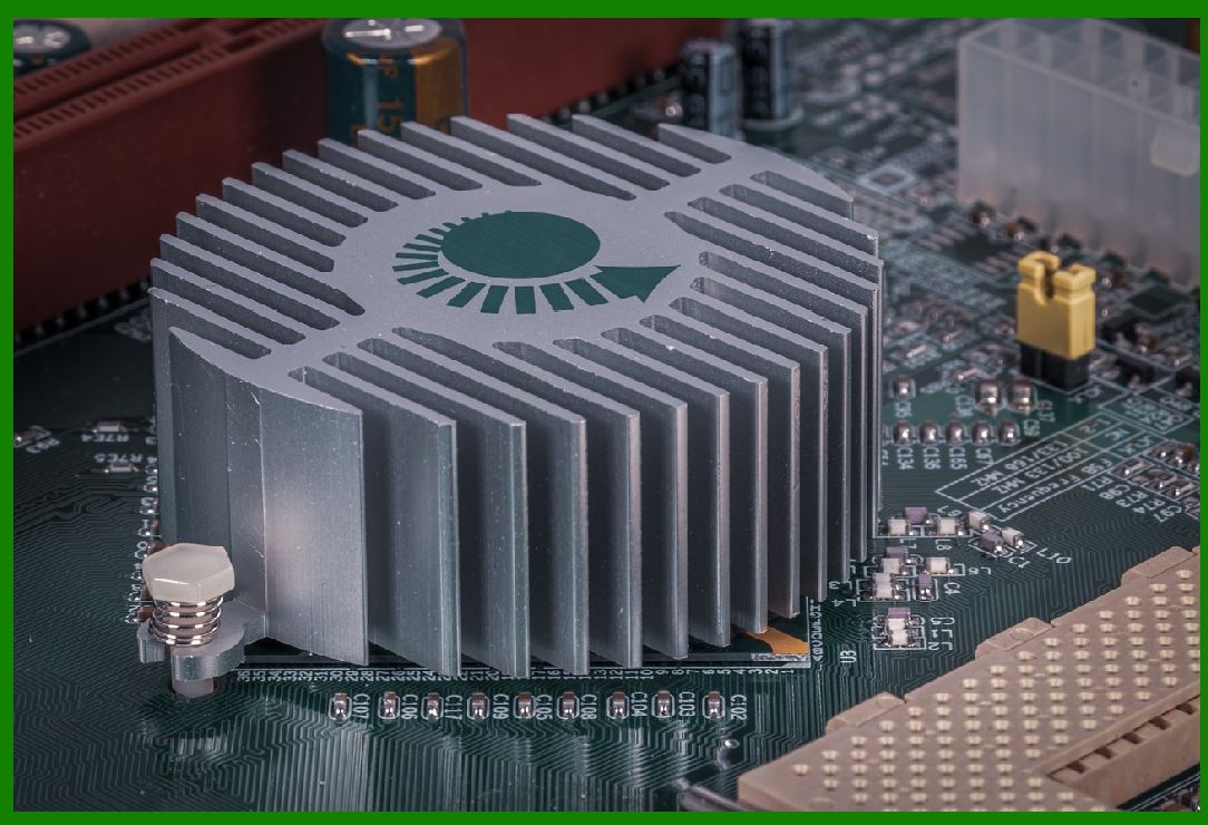
Thermal Management: Power amplifiers generate heat, and managing this heat is crucial to prevent component failure. |
Impedance Matching: Ensuring that the antenna driver circuit is properly matched to the antenna's impedance is often difficult, particularly in dynamic environments where the antenna's impedance might change based on orientation or surrounding materials. |
Interference: Electromagnetic interference from other devices operating in the same frequency range can degrade system performance. Shielding and filtering techniques are required to mitigate these effects. |
|
What challenges will it face? |
1. Power Efficiency and Consumption |
One of the main challenges in designing an antenna driver circuit for RFID systems is achieving high power efficiency while maintaining adequate signal strength. |
High Power Demand: The antenna driver circuit needs to provide sufficient power to the antenna to generate a strong electromagnetic field for communication with the RFID tags. This can be challenging, especially in systems where power supply is limited, such as in battery-powered devices. |
Power Dissipation: Power amplifiers often consume a large amount of energy, and the inefficiency of the amplifier can lead to excessive heat dissipation. This reduces the overall system efficiency and can affect the performance of the RFID reader, especially in high-duty cycle applications. |
Optimizing Power Consumption: Designers have to balance the trade-off between power consumption and signal strength. While increasing the power output of the antenna may enhance range, it will also increase energy consumption, which is a significant consideration for portable RFID readers or systems designed for long operational lifetimes. |
|
2. Thermal Management |
Thermal management is a major concern in the design of any power amplifier, and RFID antenna driver circuits are no exception. As power amplifiers are responsible for amplifying the signals to a high power level, they naturally generate heat. |
Heat Generation: Power amplifiers can easily exceed acceptable temperature limits if not properly managed. This could lead to thermal runaway, where increasing temperature causes more current to flow, which in turn generates more heat. |
Heat Dissipation: Without effective cooling solutions, the heat generated can cause damage to sensitive components, degrade performance, or shorten the lifespan of the system. Designing the circuit to manage heat through techniques like thermal vias, heat sinks, and efficient layout strategies is essential. |
Material and Component Constraints: Components used in the circuit must be capable of operating under high temperature conditions, which can increase the cost and complexity of the design. |

|
3. Impedance Matching |
Impedance matching is crucial to ensure that maximum power is transferred from the antenna driver circuit to the antenna. When there is an impedance mismatch, part of the signal is reflected back into the driver circuit, causing signal loss and inefficiency. |
Complex Matching Networks: Achieving proper impedance matching across a wide range of frequencies is challenging, particularly in systems that need to operate over varying conditions or where the environment may alter the antenna's impedance (e.g., due to proximity to metal surfaces, human bodies, or other objects). |
Dynamic Impedance Variations: In real-world applications, the impedance of an RFID antenna may vary due to environmental factors. For instance, the presence of water, metal objects, or changes in temperature can alter the impedance, causing efficiency losses or failures in communication. |
Design Complexity: The antenna driver circuit must include a robust impedance matching network that can compensate for these variations, adding complexity and requiring precise tuning of inductive and capacitive elements. |

|
4. Signal Integrity and Noise Interference |
Maintaining signal integrity while minimizing noise and interference is another significant challenge for antenna driver circuits. |
Electromagnetic Interference (EMI): RFID systems operate in crowded frequency bands, particularly in UHF and HF ranges, which are shared with other devices (e.g., Wi-Fi, Bluetooth, microwave ovens, etc.). This makes them susceptible to interference that could degrade performance. The antenna driver circuit must be designed to filter out or mitigate EMI from these sources. |
Cross-talk and Spurious Signals: Noise and spurious signals generated by the power amplifier and modulator can interfere with the clean transmission of RFID signals. To combat this, the circuit must employ filtering, shielding, and careful layout techniques to minimize noise. |
Signal Distortion: Non-linear behavior of the power amplifier, while improving efficiency, could distort the transmitted signal. This is particularly critical in applications where data integrity is paramount. In cases where signal distortion is unavoidable, error-correction techniques or advanced modulation schemes may need to be used, which can add complexity to the design. |
|
5. Component Selection and Quality |
Choosing the right components for the antenna driver circuit is essential for ensuring both performance and reliability. |
Power Amplifier Choice: Selecting the appropriate power amplifier for the specific frequency band and power requirements is difficult. The amplifier must provide sufficient power without introducing excessive distortion, and it must operate efficiently within the chosen frequency range. |
Component Tolerances: Components such as resistors, capacitors, and inductors have specific tolerances that could impact the performance of the circuit. Even small variations can affect the antenna's impedance matching or the overall signal quality. Thus, selecting high-quality components with tight tolerances becomes crucial. |
Temperature Stability: Components must be stable under varying temperature conditions. Power amplifiers and other active components tend to change their characteristics with temperature fluctuations, which can result in reduced performance or failure. Thermal compensation mechanisms are often necessary for stable operation. |
|
6. Bandwidth Limitations |
RFID systems operate across various frequency bands, each with its own set of bandwidth limitations. |
Bandwidth for Modulation: The antenna driver circuit must support the bandwidth required by the modulation scheme being used (e.g., Amplitude Shift Keying (ASK), Frequency Shift Keying (FSK), or Phase Shift Keying (PSK)). A mismatch between the available bandwidth and the modulation technique can limit the data throughput of the system. |
Wideband Operation: If the system is designed to operate over a wide frequency range, the antenna driver circuit must accommodate the full bandwidth without compromising signal quality. Achieving this across all frequencies while maintaining efficiency can be difficult, especially when the circuit needs to be compact and low-cost. |

|
7. Designing for Multiple Antennas |
In RFID systems that use multiple antennas (e.g., for multi-zone coverage or in situations where the tag's orientation may vary), the antenna driver circuit must be designed to handle switching between antennas or to drive multiple antennas simultaneously. |
Switching Complexity: The circuit must include switching elements that can seamlessly transition between antennas without causing signal loss or distortion. RF switches must operate quickly and reliably to ensure that the RFID system's communication is not interrupted. |
Power Division: If multiple antennas are used, power must be efficiently divided between the antennas without excessive losses. This could require additional circuitry to balance power output and ensure each antenna receives the correct amount of energy. |
|
8. Environmental Factors |
The environment in which the RFID system operates has a significant impact on the antenna driver circuit's performance. This includes factors like temperature variations, humidity, electromagnetic interference, and physical obstructions. |
Temperature Sensitivity: Changes in environmental temperature can cause components to behave differently, affecting performance and power efficiency. This is particularly challenging for systems that are deployed outdoors or in industrial environments where temperature fluctuations can be extreme. |
Electromagnetic Interference (EMI): As RFID systems operate in radio frequency ranges, they are vulnerable to EMI from surrounding electronics, machinery, or even natural phenomena. Ensuring the antenna driver circuit is well-shielded against EMI is critical to maintaining signal integrity and avoiding system failures. |
Material Interaction: The materials present in the environment can affect the RFID system's operation. For example, metal surfaces or liquids can cause changes in the electromagnetic field, potentially disrupting the communication between the reader and the tags. The antenna driver circuit must be designed to mitigate the effects of such materials, and often this means using advanced filtering or adaptive algorithms. |
|
9. Regulatory Compliance |
RFID systems are subject to a range of regulatory standards to ensure that their electromagnetic emissions do not interfere with other communication systems or cause harm to users. |
Power Limitations: Regulatory bodies, such as the Federal Communications Commission (FCC) in the United States, impose limits on the amount of power that can be transmitted by RFID systems to avoid interference with other communication devices. The antenna driver circuit must be designed to operate within these regulatory limits while still providing adequate range and signal strength. |
Frequency Bands: Different regions have different frequency bands allocated for RFID use, and the antenna driver circuit must be designed to comply with these regional requirements. This could mean designing circuits that can operate in multiple frequency bands (e.g., UHF 860-960 MHz, HF 13.56 MHz) or using frequency-hopping techniques to avoid interference with other devices operating in the same spectrum. |
|
10. Cost and Size Constraints |
Finally, as with any electronics system, there are cost and size constraints that impact the design of the antenna driver circuit. |
Cost Efficiency: While high-end components can provide better performance and reliability, they can also increase the overall cost of the system. In consumer or mass-market applications, cost efficiency is often prioritized, which may limit the choice of components or the complexity of the design. |
Size Limitations: In many RFID applications, especially handheld devices or embedded systems, there are size limitations. The antenna driver circuit must be compact and efficient, which may involve trade-offs between performance and size. |

|
Conclusion |
The design of an RFID antenna driver circuit is a complex task that involves overcoming several challenges, ranging from power efficiency and thermal management to signal integrity and impedance matching. These challenges require careful consideration of the environment, component selection, and regulatory compliance, along with trade-offs between performance, cost, and size. Successful design will require a balance between these various factors to ensure reliable, efficient, and effective RFID communication. |
|
Do a barcode reader needs the Antenna Driver Circuit? |
No, a barcode reader does not require an antenna driver circuit. |
Key Differences Between Barcode Readers and RFID Systems: |
1.Technology Type: |
Barcode Readers: Barcode readers use optical technology to scan and decode printed barcodes. They typically use a laser or LED light source to illuminate the barcode and a sensor to detect the reflected light, which is then processed to extract the encoded information. No radio-frequency signals or antennas are involved in barcode scanning. |
RFID Readers: RFID (Radio Frequency Identification) readers, on the other hand, rely on radio waves to communicate with RFID tags. They require an antenna driver circuit to generate and transmit electromagnetic signals to power passive RFID tags or communicate with active ones. |
|
2.Need for an Antenna: |
Barcode Readers: These readers do not use antennas. They rely on a camera or laser scanner to capture the image or reflection of a barcode. They only need optical components (like a laser or CCD camera) and electronic components for signal processing. |
RFID Readers: An RFID reader requires an antenna driver circuit to generate RF signals through the antenna, enabling communication with RFID tags. |
Why Barcode Readers Do Not Need an Antenna Driver Circuit: |
No Radio Frequency Transmission: A barcode reader does not transmit or receive radio frequency (RF) signals. Instead, it uses visible light or infrared light to detect barcodes. Hence, there is no need for components like power amplifiers, modulators, or impedance matching networks that are essential in an RFID system with an antenna driver circuit. |
No Electromagnetic Field Generation: Since barcode readers don't rely on generating electromagnetic fields for communication, there's no need for the driver circuitry that powers an antenna, as is the case in RFID systems. |
|
Conclusion: |
A barcode reader and an RFID reader serve similar purposes (scanning or reading data), but their underlying technologies are fundamentally different. Barcode readers operate optically, while RFID readers use radio waves, necessitating components like an antenna driver circuit. |
 cs@easiersoft.com