RFID Reader's Antenna and Its Role in the Circuit |
Radio Frequency Identification (RFID) systems have become an integral part of a wide range of industries, from logistics and supply chain management to healthcare and security. The technology relies heavily on the interaction between RFID readers and RFID tags, which communicate through electromagnetic waves. At the core of this communication system is the RFID antenna, a critical component that plays a central role in transmitting and receiving signals between the RFID reader and the tags. |
This article delves into the detailed aspects of the RFID reader's antenna, its role in the circuit, design considerations, and how it impacts the overall performance of an RFID system. We will explore different types of antennas, operating frequencies, the interaction of the antenna with RFID tags, and factors that influence antenna performance. |

|
1. Introduction to RFID Antennas |
RFID technology uses radio waves to transmit data between an RFID reader and an RFID tag. The antenna in an RFID reader is the key component responsible for creating the electromagnetic field necessary for communication. Essentially, it converts electrical signals from the reader into radio frequency signals (RF) and vice versa. Without the antenna, the system would not be able to exchange data between the reader and the tag. |
The antenna is responsible for generating a radio frequency field around the RFID reader, which activates the RFID tags within its range. RFID antennas come in various shapes, sizes, and designs, depending on the specific requirements of the system, such as communication range, frequency, and environmental factors. |

|
2. The Role of the RFID Antenna |
The primary role of the RFID antenna in a reader is to facilitate wireless communication by creating and detecting electromagnetic waves. These waves are critical in the transmission of energy and data between the reader and the RFID tags. When the antenna transmits a signal, it generates an electromagnetic field that propagates through the air. This field interacts with RFID tags that are within range, activating them. The tags then reflect a signal back to the antenna, allowing the reader to collect information such as the unique identification number (UID) stored in the tag's memory. |
The effectiveness of this communication relies on several factors: |
Transmission of Energy: The antenna sends out a signal that powers passive RFID tags. Tags absorb this energy and respond with their stored information. |
Receiving Signals: The antenna also receives signals from the RFID tags, which are typically reflected or modulated waves containing data. |
Frequency Selection: The antenna determines the frequency at which the RFID system operates. Different frequencies have different properties, such as range and data transmission speed, which affect system performance. |

|
3. Types of RFID Antennas |
RFID antennas are designed in various forms, each suited to specific applications based on factors such as range, form factor, and the type of RFID system (active, passive, or semi-passive). The choice of antenna depends on the system's needs, including how far it needs to read tags, the type of environment in which it will operate, and whether it requires direct or indirect interaction with the tags. Below are the common types of RFID antennas: |
3.1 Loop Antennas |
Loop antennas are one of the most widely used types of RFID antennas, particularly in passive RFID systems. They consist of a single loop or a coil of wire, usually in a circular or square shape, and are designed to generate a magnetic field. When the antenna transmits energy, the loop creates a fluctuating magnetic field, which induces a current in the RFID tag's coil. This interaction powers the tag and allows it to send data back to the reader. |
Key characteristics of loop antennas: |
Range: Typically used for short-range communication, from a few centimeters to several meters, depending on the size and power of the loop. |
Orientation: These antennas are often sensitive to orientation, meaning the tag must be aligned with the loop for efficient communication. |
Efficiency: The efficiency of loop antennas can vary based on the frequency used and the design of the loop. They are often tuned for a specific frequency to maximize their performance. |
3.2 Patch Antennas |
Patch antennas are flat, low-profile antennas typically made of metal, designed to be mounted on a surface. They are widely used in RFID systems that require higher range and better directional control. Patch antennas are often used in active and semi-passive RFID systems, where communication ranges need to be extended. |
Key characteristics of patch antennas: |
Range: They offer a longer communication range compared to loop antennas, typically up to 10 meters or more, depending on the power and frequency. |
Directional: Patch antennas are more directional than loop antennas, meaning they focus the signal in a specific direction. This helps to concentrate energy and improve communication range and reliability. |
Compact Design: Their compact, flat design makes them easy to integrate into various RFID applications, such as access control systems and tracking solutions. |
3.3 Dipole Antennas |
Dipole antennas are one of the simplest forms of antennas and consist of two identical conductive elements, usually metal rods. They are often used in RFID systems where simplicity, low cost, and ease of integration are important. Dipole antennas are generally effective for medium-range applications. |
Key characteristics of dipole antennas: |
Range: The range of dipole antennas is typically between that of loop and patch antennas. They can effectively communicate at ranges up to several meters. |
Omnidirectional: Dipole antennas radiate energy in an omnidirectional pattern, meaning they transmit and receive signals in all directions. This makes them suitable for systems where the tag's orientation may vary. |
Cost-Effective: Dipole antennas are generally low in cost, which makes them suitable for large-scale applications like inventory management. |
3.4 Circular Polarized Antennas |
Circularly polarized antennas are often used when the RFID tags are subject to different orientations. They transmit electromagnetic waves with a rotating electric field, which allows the signal to reach tags regardless of their alignment or orientation. This makes them ideal for environments where the tags may not be positioned in a predictable manner. |
Key characteristics of circular polarized antennas: |
Orientation Flexibility: Circular polarization allows communication with tags at different orientations, improving the accuracy and efficiency of the system. |
Range: These antennas provide a balance between range and reliability, making them useful in both active and passive RFID systems. |

|
4. Operating Frequency of RFID Antennas |
The operating frequency is a critical factor in determining the performance of an RFID system. Different frequencies have distinct propagation characteristics, such as range, data transfer rate, and sensitivity to interference. RFID systems typically operate in the following frequency bands: |
4.1 Low Frequency (LF) - 125 kHz to 134 kHz |
Low-frequency RFID systems are often used for short-range applications, such as animal tracking and access control. LF antennas tend to have a shorter communication range (typically up to 10 cm) but are less susceptible to interference from metals and liquids. |
4.2 High Frequency (HF) - 13.56 MHz |
High-frequency RFID systems are more commonly used for applications like smart cards, library management, and contactless payment systems. HF antennas offer medium-range communication, typically from 10 cm to 1 meter. They are more efficient at transmitting and receiving data than LF antennas but are still relatively short-range. |
4.3 Ultra High Frequency (UHF) - 860 MHz to 960 MHz |
UHF RFID systems are widely used in supply chain management, asset tracking, and inventory management due to their long-range capabilities (typically 1 to 12 meters). UHF antennas can read multiple tags simultaneously and offer higher data transfer rates. However, they can be affected by interference from metals and liquids, which may cause signal degradation. |
4.4 Microwave - 2.4 GHz to 5.8 GHz |
Microwave RFID systems provide very high data transfer rates and long-range communication (up to 100 meters or more). These systems are often used in applications that require high-speed, real-time data transmission, such as toll collection and logistics tracking. Microwave RFID antennas are more sensitive to environmental factors and require careful placement to avoid signal interference. |
|
5. Factors Affecting Antenna Performance |
Several factors influence the performance of an RFID antenna and, by extension, the overall efficiency of the RFID system. These factors include the design of the antenna, environmental conditions, frequency range, and the characteristics of the RFID tags. |
5.1 Antenna Gain |
Antenna gain refers to how effectively an antenna directs or concentrates energy in a particular direction. A high-gain antenna focuses energy in a specific direction, providing a longer range for communication. A low-gain antenna, on the other hand, radiates energy more evenly in all directions, which is useful for applications where omnidirectional coverage is required. |
5.2 Polarization |
Polarization refers to the orientation of the electromagnetic waves emitted by the antenna. For optimal communication, the polarization of the reader's antenna should match the polarization of the RFID tag's antenna. Circular polarization is often used to eliminate the orientation dependence, but linear polarization is more common in simple systems. |
5.3 Environmental Factors |
Environmental conditions, such as the presence of metal, liquids, or other materials that can interfere with radio waves, can significantly affect the performance of RFID antennas. Metals tend to reflect and absorb radio waves, leading to signal loss, while liquids can cause signal attenuation. Antennas must be designed to operate efficiently in the specific environment they are used in. |
5.4 Antenna Impedance Matching |
Impedance matching ensures that the antenna is properly matched with the RFID reader's transmission line to minimize signal reflection and maximize energy transfer. An impedance mismatch can result in power losses, signal distortion, or reduced communication range. |
|
6. Conclusion |
The RFID reader's antenna is a vital component in the RFID system, playing a central role in the system's ability to communicate with RFID tags. Whether loop, patch, dipole, or circular polarized, the antenna must be designed carefully to meet the specific requirements of the application. Its function is to generate and detect radio frequency signals, facilitating the transfer of data and energy between the reader and the tags. |
Factors such as frequency, gain, polarization, and environmental considerations all contribute to the efficiency of the antenna. The design choices made for the antenna directly affect the range, reliability, and speed of the RFID system. Understanding the intricate details of RFID antennas and their role in the circuit is essential for developing efficient and high-performance RFID solutions across a range of industries. |
|
What are the common failures cause by the RFID reader's Antenna Circuit? How to check and fix them? |
RFID systems are reliable, but like any technology, they can experience issues, especially within the antenna circuit. These failures can significantly impact the system's performance, leading to problems such as poor read range, unreliable data transmission, or complete system failure. The RFID reader's antenna circuit plays a critical role in the communication process, so understanding the common issues that arise and how to diagnose and fix them is crucial for maintaining optimal system performance. |
1. Common Failures in RFID Antenna Circuits |
Below are the most common issues caused by the RFID reader's antenna circuit, along with their causes, symptoms, and potential fixes. |
1.1 Poor or No Signal Reception |
Cause: |
Antenna Malfunction: One of the most common causes of poor or no signal reception is a malfunctioning antenna, which may occur due to damage, wear, or manufacturing defects. |
Antenna Misalignment: The antenna may not be positioned correctly relative to the RFID tags. If the tags are not in the ideal orientation or range, the antenna may not be able to receive the signal effectively. |
Impedance Mismatch: If the impedance of the antenna does not match the impedance of the reader's transmitter circuit (usually 50 ohms), signal reflection can occur, causing a weak or intermittent signal reception. |
Interference: Electromagnetic interference from nearby equipment, metal objects, or liquids can distort or block the signal, making it difficult for the antenna to receive data from the tag. |
Symptoms: |
The RFID reader fails to read tags, or it only reads tags intermittently. |
The system has a short read range, or no tags are detected within the expected range. |
Data transfer is slow or unreliable. |
How to Check and Fix: |
Antenna Inspection: Visually inspect the antenna for any signs of physical damage, such as cuts, corrosion, or breakage. Ensure that the antenna is securely connected to the RFID reader's circuitry. |
Repositioning: Adjust the antenna's position and orientation to ensure that the RFID tags are within the optimal reading area and properly aligned with the antenna's field. |
Impedance Matching: Use a network analyzer to check the impedance of the antenna and ensure that it is properly matched with the reader's output impedance. If necessary, add a matching network (e.g., a matching transformer or circuit) to correct any impedance mismatch. |
Check for Interference: Ensure that the antenna is not located near sources of interference, such as large metal objects, motors, or other electronics. Reposition the antenna to a different location if interference is suspected. |
Cable Check: Inspect the cable connecting the antenna to the reader for any signs of damage, such as frays or kinks. Damaged cables can lead to signal loss. |

|
1.2 Signal Overload or Saturation |
Cause: |
Too Strong Signal: In some cases, the antenna may be receiving too strong a signal, which leads to overload or saturation of the receiver circuit. This can happen when the antenna is placed too close to the RFID tags or if the reader is outputting too much power. |
Proximity to Power Lines or High-Powered RF Sources: If the antenna is located near power lines, high-powered radio frequency transmitters, or other electromagnetic sources, it could receive interference or an excessive signal. |
Symptoms: |
The RFID reader fails to read tags correctly, or it continuously reads the same tag. |
The reader displays a 'signal saturation' warning or an error message indicating an overload. |
The tags do not respond properly, or only partial data is returned. |
How to Check and Fix: |
Reduce Power Output: If possible, reduce the power output of the RFID reader to prevent the antenna from receiving an overly strong signal. Many readers have adjustable power settings, so lower the power and test the system again. |
Increase Distance: Move the antenna away from the tags to prevent close-range saturation. Ensure that the tags are within the optimal operating distance for your RFID system. |
Use a Power Limiter: If the issue persists, consider using a power limiter or attenuator in the circuit to reduce the power being transmitted to the antenna. |
Reposition the Antenna: Ensure the antenna is not positioned near large metal objects or high-powered RF transmitters that might be causing interference or excessive signal strength. |

|
1.3 Poor Read Range or Inconsistent Readability |
Cause: |
Antenna Design or Orientation: The antenna may be poorly designed for the specific frequency or environment in which it is used. For instance, certain antenna types (such as loop antennas) are highly sensitive to orientation, and misalignment can reduce read range. |
Antenna Misalignment: If the antenna is not aligned properly with the RFID tags, the signal strength may be reduced, leading to a short read range or intermittent performance. |
Environmental Factors: Environmental conditions such as metal, liquids, or large obstacles can interfere with the radio waves, reducing the effective range of the antenna. |
Damaged Components: Physical damage or aging of the antenna's components (such as the coil or PCB) can degrade its ability to transmit and receive signals effectively. |
Symptoms: |
RFID tags are only read intermittently, or the reader fails to detect tags within the expected range. |
The reader fails to detect tags even when they are within proximity. |
How to Check and Fix: |
Test with Different Antennas: Swap out the existing antenna for a known working one to see if the issue persists. If the problem resolves with the new antenna, the original antenna is likely damaged or improperly designed. |
Adjust Antenna Position: Ensure that the antenna is positioned properly in relation to the tags. Consider using a different antenna type, such as a patch or circular polarized antenna, if the current antenna does not provide sufficient range. |
Environmental Adjustments: Test the system in a different environment to ensure that metal or liquid objects are not obstructing the signals. If the environment is problematic, consider using specialized antennas designed for challenging conditions. |
Inspect Antenna Components: Check for any physical damage or signs of wear on the antenna itself, such as cracks, corrosion, or broken connectors. If damaged, replace the antenna or its components. |

|
1.4 Antenna Circuit Short Circuit or Open Circuit |
Cause: |
Short Circuit: A short circuit can occur in the antenna circuit due to faulty components, damaged connections, or incorrect soldering. This causes the antenna to behave abnormally or stop working entirely. |
Open Circuit: An open circuit can occur when there is a break in the antenna's wiring or connection, which prevents the reader from receiving or transmitting signals. |
Symptoms: |
The reader fails to recognize or read any RFID tags. |
The system might display an error message indicating a 'circuit failure' or 'antenna disconnection.' |
The reader may not turn on at all or may display a 'no antenna' warning. |
How to Check and Fix: |
Visual Inspection: Inspect the antenna circuit carefully for signs of visible damage, such as burnt areas, broken connections, or loose components. Look for any wires that are not properly connected. |
Multimeter Testing: Use a multimeter to check for continuity in the antenna circuit. If you find an open circuit, check the connections and components along the path. If you detect a short, identify the faulty component causing the short circuit. |
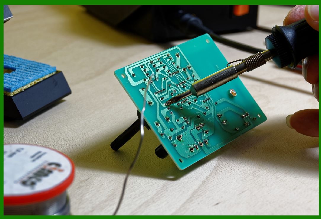
Soldering and Connections: If there are any poor or loose solder joints, reflow the solder or re-solder the components to ensure a solid connection. |
Replace Damaged Components: If a specific component, such as a resistor or capacitor, is damaged, replace it with a new one to restore proper circuit functionality. |
|
1.5 Antenna Detuning |
Cause: |
Frequency Drift: Antennas are designed to operate at specific frequencies. If the antenna becomes detuned due to environmental factors, such as temperature fluctuations or aging of the materials, the performance may degrade. |
Component Damage: Physical damage to the antenna, such as a break in the antenna coil or PCB trace, can cause detuning, reducing the efficiency of the antenna. |
Symptoms: |
The RFID reader fails to read tags at the expected distances. |
The reader might struggle to detect tags consistently or at all. |
How to Check and Fix: |
Test with Antenna Analyzer: Use an antenna analyzer to check the resonance of the antenna. This device can help identify whether the antenna is tuned to the correct frequency or if it has drifted. |
Replace or Re-tune the Antenna: If detuning is detected, either replace the antenna or adjust its tuning components to bring it back to the proper resonance frequency. |
|
2. Conclusion |
The RFID reader's antenna circuit is a vital component of the RFID system, and problems with it can lead to communication failures, poor range, or unreliable data. Understanding the common causes of antenna circuit failures, such as signal issues, circuit damage, or environmental interference, is essential for effective troubleshooting. |
To check and fix these issues, it's important to inspect the antenna, test the circuit for continuity, and adjust the power settings or environmental factors that may be contributing to the problem. Regular maintenance and testing can help ensure that RFID systems remain efficient and functional, minimizing downtime and ensuring smooth operation in critical applications. |

|
What new technologies will improve the function of the RFID reader's Antenna and reduce the failure rate? |
The field of RFID technology has seen significant advancements over the years, especially in improving the performance of RFID systems and reducing the failure rate of components such as the RFID reader's antenna. Innovations in materials, antenna designs, power management, and signal processing are all contributing to better efficiency, longer range, and more reliable communication. Below are some of the emerging technologies that are likely to improve the function of the RFID reader's antenna and reduce the failure rate: |
1. Advanced Materials for Antenna Design |
1.1 Metamaterials |
Metamaterials are artificially structured materials engineered to have properties that may not exist in naturally occurring materials. These materials can be used to enhance the performance of RFID antennas by improving their efficiency, range, and selectivity. |
Benefit: Metamaterials can be designed to manipulate electromagnetic waves in a way that enhances signal transmission and reception. This can reduce the chances of signal degradation or failure due to interference from metal surfaces or liquids, making them particularly useful in challenging environments (e.g., warehouses or factories with heavy machinery). |
Example: A metamaterial-based RFID antenna might allow for more precise control over the antenna's radiation pattern, improving read range and system efficiency. |
1.2 Graphene and Carbon Nanotubes |
Graphene and carbon nanotubes are materials with extraordinary electrical, thermal, and mechanical properties. Their integration into RFID antenna designs could dramatically reduce the antenna's size while improving its efficiency. |
Benefit: Graphene-based RFID antennas could lead to lighter, more flexible antennas with better conductivity and reduced signal loss. Carbon nanotubes are also highly resistant to environmental wear, making them ideal for reducing failure rates caused by corrosion or physical damage. |
Example: Antennas made from these materials could withstand harsh environments and provide more reliable signal transmission over longer distances. |

|
2. Flexible and Wearable RFID Antennas |
As RFID technology expands into new sectors like wearable devices, healthcare, and logistics, flexible and wearable antennas are becoming increasingly important. The use of flexible substrates, such as plastic or fabric-based antennas, could make RFID systems more adaptable and reduce physical wear and tear. |
Benefit: Flexible RFID antennas can be integrated into clothing, packaging, and even medical devices without sacrificing performance. Their resilience to deformation and ability to function on curved surfaces could reduce antenna failure caused by environmental stress or movement. |
Example: RFID antennas embedded into wearable health monitors or smart clothing can maintain reliable signal transmission even under movement or bending, minimizing failure rates in active environments. |

|
3. Advanced Signal Processing and Software Algorithms |
3.1 Digital Signal Processing (DSP) Enhancements |
Digital Signal Processing (DSP) technologies can be applied to the RFID reader's antenna circuit to optimize the signal received from the tags and minimize noise or interference. By incorporating more sophisticated DSP algorithms, RFID readers can better filter out unwanted signals, improving the reliability of communication. |
Benefit: Improved signal processing can compensate for weak or degraded signals, ensuring more reliable communication with tags, even in challenging environments (e.g., near metal surfaces or dense liquid). |
Example: A DSP algorithm that enhances the reader's ability to detect and decode signals from tags in noisy environments can increase the read rate and reduce the chances of communication failures. |
3.2 Machine Learning and AI for Adaptive Signal Processing |
Machine learning (ML) and artificial intelligence (AI) can be used to create adaptive RFID systems that learn from their environment and optimize antenna performance over time. These systems could automatically adjust transmission power, antenna positioning, or signal frequency to improve performance based on real-time conditions. |
Benefit: AI-based systems can dynamically adapt to changes in the environment, such as interference or changes in tag orientation, ensuring reliable performance and minimizing failure rates. |
Example: An AI algorithm might adjust the read zone of an antenna or change its polarization angle depending on the position and orientation of tags, improving communication stability and range. |

|
4. Multi-Polarization and Multi-Band Antennas |
RFID antennas that support multiple polarizations or multiple frequency bands are becoming more prevalent in modern systems. These antennas can operate across different frequencies and polarization modes, offering better performance and reliability in various environments. |
4.1 Circular and Dual-Polarized Antennas |
Antennas with circular polarization or dual-polarization (both vertical and horizontal polarization) can increase the range and reliability of RFID systems, especially in environments where the orientation of the tag cannot be controlled. |
Benefit: These antennas can communicate with tags regardless of their orientation, which reduces failures caused by misalignment between the tag and the reader's antenna. |
Example: A dual-polarized antenna might be used in an RFID system in a warehouse where the tags are placed on items in various orientations. The reader will be able to detect all tags, reducing failure rates due to orientation issues. |
4.2 Wideband Antennas |
Wideband antennas can support a broad range of frequencies, allowing them to be used in various RFID applications without needing to change the antenna when the system's frequency needs to be adjusted. |
Benefit: By covering a broader frequency spectrum, wideband antennas allow RFID systems to operate efficiently in multiple environments or across different RFID standards (e.g., HF, UHF, or microwave). |
Example: A wideband antenna could be used in retail or logistics applications where different RFID tags may operate at different frequencies. This reduces failure rates by enabling the reader to handle a variety of tag types and frequencies. |

|
5. Adaptive Power Management Systems |
Adaptive power management is a growing trend in RFID systems, allowing antennas to dynamically adjust the power levels based on the environment and the distance to the tags. This can help prevent signal overload or saturation, especially in environments where the tags are located at varying distances from the reader. |
Benefit: By adjusting the power based on the tag's proximity and the surrounding environment, adaptive power management can optimize signal strength, extend battery life in mobile RFID readers, and minimize interference or overload issues. |
Example: A smart power management system can automatically reduce transmission power when the antenna detects that tags are within close range, preventing signal overload and improving overall system performance. |

|
6. Near Field Communication (NFC) Enhancements |
NFC, a subset of RFID technology, has seen major advancements that could also benefit RFID reader antennas. The use of NFC for short-range communication has grown in applications like payment systems, access control, and asset tracking. New technologies within NFC could also improve the efficiency of RFID antenna systems. |
Benefit: Improved NFC chip designs and antenna layouts will allow for higher-density, more efficient communication over short distances, leading to fewer signal loss issues and higher read rates. |
Example: NFC systems with improved antennas will be able to read tags through more complex materials (e.g., metal or liquid), reducing failures in specific environments like medical equipment management. |

|
7. Integration of RFID with IoT and 5G |
7.1 Internet of Things (IoT) Integration |
As RFID systems are integrated into the broader Internet of Things (IoT) ecosystem, RFID antennas may benefit from new communication protocols that allow them to interact with IoT sensors, networks, and cloud-based systems more efficiently. |
Benefit: RFID antennas integrated with IoT networks can take advantage of real-time monitoring and predictive analytics to preemptively detect and address issues, such as signal degradation or hardware malfunctions. |
Example: IoT-connected RFID systems might automatically flag antenna performance issues or failure trends, alerting maintenance teams before a failure occurs, thereby reducing downtime and improving system reliability. |
7.2 5G Connectivity |
With the rollout of 5G networks, RFID systems may benefit from the higher bandwidth and lower latency that 5G offers. RFID antennas integrated with 5G technology could transmit data more rapidly and securely, especially in environments with dense tag populations or high data requirements. |
Benefit: 5G-enabled RFID systems could support faster read times, more stable communication, and higher data throughput, while reducing interference and communication failures caused by network congestion. |
Example: In a high-speed logistics operation, RFID antennas linked to 5G networks could read tags in real-time and update inventory data instantaneously, reducing delays and failures caused by data transmission issues. |

|
8. Wireless Power Transfer for RFID Tags |
Wireless power transfer technologies, such as resonant inductive coupling, can help improve the performance of passive RFID tags, reducing the failure rate caused by weak tag power sources. These technologies enable RFID readers to supply power to tags even at greater distances. |
Benefit: By using wireless power transfer, RFID readers can ensure that tags are continuously powered, even if they are located further away or in challenging environments. This reduces failures caused by weak or dead tags. |
Example: In a warehouse environment, the use of wireless power transfer could enable tags to remain powered throughout the reading process, improving the system's read reliability and reducing failures. |
|
Conclusion |
The evolution of RFID technology is driving improvements in the design, functionality, and reliability of RFID reader antennas. New materials, such as metamaterials and graphene, are enabling smaller, more efficient antennas with enhanced performance. At the same time, advancements in signal processing, AI-based optimization, and adaptive power management are enhancing the reliability and versatility of RFID systems. |
By adopting these technologies, RFID systems can achieve more accurate and consistent performance, even in challenging environments. These advancements not only improve the functionality of the RFID reader's antenna but also reduce the failure rate, ensuring more reliable communication and data transmission in various applications. |
 cs@easiersoft.com